Page 4294 of 4770
SR06E±01
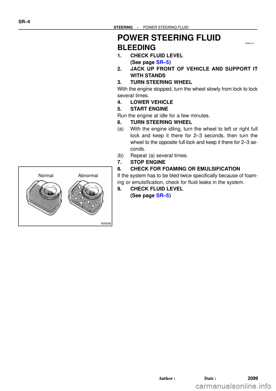
R09599
Normal Abnormal SR±4
± STEERINGPOWER STEERING FLUID
2099 Author�: Date�:
POWER STEERING FLUID
BLEEDING
1. CHECK FLUID LEVEL
(See page SR±5)
2. JACK UP FRONT OF VEHICLE AND SUPPORT IT
WITH STANDS
3. TURN STEERING WHEEL
With the engine stopped, turn the wheel slowly from lock to lock
several times.
4. LOWER VEHICLE
5. START ENGINE
Run the engine at idle for a few minutes.
6. TURN STEERING WHEEL
(a) With the engine idling, turn the wheel to left or right full
lock and keep it there for 2±3 seconds, then turn the
wheel to the opposite full lock and keep it there for 2±3 se-
conds.
(b) Repeat (a) several times.
7. STOP ENGINE
8. CHECK FOR FOAMING OR EMULSIFICATION
If the system has to be bled twice specifically because of foam-
ing or emulsification, check for fluid leaks in the system.
9. CHECK FLUID LEVEL
(See page SR±5)
Page 4295 of 4770

or less
Engine Idling Engine Stopped
± STEERINGPOWER STEERING FLUID
SR±5
2100 Author�: Date�:
INSPECTION
1. CHECK FLUID LEVEL
(a) Keep t")
SR06F±01
R00427
R09599
Normal Abnormal
R11562
5 mm (0.2 in.)
or less
Engine Idling Engine Stopped
± STEERINGPOWER STEERING FLUID
SR±5
2100 Author�: Date�:
INSPECTION
1. CHECK FLUID LEVEL
(a) Keep the vehicle level.
(b) With the engine stopped, check the fluid level in the oil
reservoir.
If necessary, add fluid.
Fluid: ATF DEXRON® II or III
HINT:
Check that the fluid level is within the HOT LEVEL range on the
reservoir. If the fluid is cold, check that it is within the COLD
LEVEL range.
(c) Start the engine and run it at idle.
(d) Turn the steering wheel from lock to lock several times to
boost fluid temperature.
Fluid temperature: 80°C (176°F)
(e) Check for foaming or emulsification.
If there is foaming or emulsification, bleed power steering
system.
(See page SR±4)
(f) With the engine idling, measure the fluid level in the oil
reservoir.
(g) Stop the engine.
(h) Wait a few minutes and remeasure the fluid level in the oil
reservoir.
Maximum fluid level rise: 5 mm (0.20 in.)
If a problem is found, bleed power steering system.
(See page SR±4)
(i) Check the fluid level.
Page 4296 of 4770
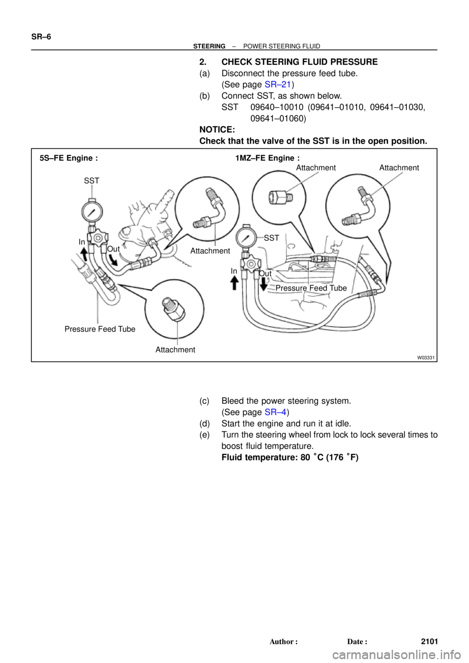
W03331
Attachment
Pressure Feed TubePressure Feed Tube SST
Out In 5S±FE Engine : 1MZ±FE Engine :
Out In
AttachmentAttachment Attachment
SST SR±6
± STEERINGPOWER STEERING FLUID
2101 Author�: Date�:
2. CHECK STEERING FLUID PRESSURE
(a) Disconnect the pressure feed tube.
(See page SR±21)
(b) Connect SST, as shown below.
SST 09640±10010 (09641±01010, 09641±01030,
09641±01060)
NOTICE:
Check that the valve of the SST is in the open position.
(c) Bleed the power steering system.
(See page SR±4)
(d) Start the engine and run it at idle.
(e) Turn the steering wheel from lock to lock several times to
boost fluid temperature.
Fluid temperature: 80 °C (176 °F)
Page 4297 of 4770

Z15498
Oil
PS Gear
Closed
SSTPS Vane
Pump Reservoir
Z15499
Oil
PS Gear
SSTPS Vane
Pump Reservoir
Open
Z15500
Oil
PS Gear
SSTPS Vane
Pump Reservoir
Lock Position
± STEERINGPOWER STEERING FLUID
SR±7
2102 Author�: Date�:
(f) With the engine idling, close the valve of the SST and ob-
serve the reading on the SST.
Minimum fluid pressure:
7,845 kPa (80 kgf´cm
2, 1,138 psi)
NOTICE:
�Do not keep the valve closed for more than 10 se-
conds.
�Do not let the fluid temperature become too high.
(g) With the engine idling, open the valve fully.
(h) Measure the fluid pressure at engine speeds of 1,000 rpm
and 3,000 rpm.
Difference fluid pressure:
490 kPa (5 kgf´cm
2, 71 psi) or less
NOTICE:
Do not turn the steering wheel.
(i) With the engine idling and valve fully opened, turn the
steering wheel to full lock.
Minimum fluid pressure:
7,845 kPa (80 kgf´cm
2, 1,138 psi)
NOTICE:
�Do not maintain lock position for more than 10 se-
conds.
�Do not let the fluid temperature become too high.
(j) Disconnect the SST.
(k) Connect the pressure feed tube.
(See page SR±28)
(l) Bleed the power steering system.
(See page SR±4)
Page 4298 of 4770
R07653
SR06G±01
F01477
SR±8
± STEERINGSTEERING WHEEL
2103 Author�: Date�:
STEERING WHEEL
INSPECTION
1. CHECK STEERING WHEEL FREEPLAY
With the vehicle stopped and tires facing straight ahead, rock
the steering wheel gently back and forth with light finger pres-
sure.
Freeplay should not exceed the maximum.
Maximum freeplay: 30 mm (1.18 in.)
2. CHECK STEERING EFFORT
(a) Center the steering wheel.
(b) Remove the steering wheel pad.
(See page SR±11)
(c) Start the engine and run it at idle.
(d) Measure the steering effort in both directions.
Reference: 5.9 N´m (60 kgf´cm, 52 in.´lbf)
HINT:
Be sure to consider the tire type, pressure and contact surface
before making your diagnosis.
(e) Torque the steering wheel set nut.
Torque: 35 N´m (360 kgf´cm, 26 ft´lbf)
(f) Install the steering wheel pad.
(See page SR±16)
Page 4300 of 4770
F01476
Key Unlock Warning Switch
Column Upper Bracket Ignition Switch
Energy Absorbing PlateTransponder Key Coil Key Cylinder Lamp Assembly
Key
Interlock
Solenoid Key Cylinder
Transponder Key
Amplifier
Energy Absorbing Plate
Guide� Energy Absorbing Clip
Energy Absorbing Plate
Energy Absorbing Plate
Guide
� Energy Absorbing Clip Column TubeTilt Lever
Return Spring
� Tapered±Head Bolt Column Upper Tube Turn Signal Bracket
Lower Column Tube AttachmentColumn Tube Support
7 (70, 61 in.´lbf)
19 (195, 14)
N´m (kgf´cm, ft´lbf): Specified torque
� Non±reusable partw/ ENGINE IMMOBILISER SYSTEM:
A/T: SR±10
± STEERINGTILT STEERING COLUMN
2105 Author�: Date�:
Page 4303 of 4770

SR06J±01
W03333
Screw Extractor
W03334
± STEERINGTILT STEERING COLUMN
SR±13
2108 Author�: Date�:
DISASSEMBLY
NOTICE:
When using a vise, do not overtighten it.
1. w/ ENGINE IMMOBILISER SYSTEM:
REMOVE TRANSPONDER KEY COIL WITH KEY CYL-
INDER LAMP ASSEMBLY
Remove the screw.
2. w/ ENGINE IMMOBILISER SYSTEM:
REMOVE KEY CYLINDER LAMP ASSEMBLY
Remove the lamp assembly from the key coil.
3. w/o ENGINE IMMOBILISER SYSTEM:
REMOVE KEY CYLINDER LAMP ASSEMBLY
Remove the screw.
4. REMOVE COLUMN UPPER BRACKET AND COLUMN
UPPER CLAMP
(a) Using a centering punch, mark the center of the 2 ta-
pered±head bolts.
(b) Using a 3±4 mm (0.12±0.16 in.) drill, drill into the 2 bolts.
(c) Using a screw extractor, remove the 2 bolts.
5. REMOVE TURN SIGNAL BRACKET
Remove the 2 bolts.
6. REMOVE TILT LEVER RETURN SPRING
7. REMOVE COLUMN TUBE SUPPORT
(a) Remove the bolt and washer.
(b) Remove the tube support with lower column tube attach-
ment.
(c) Remove the tube attachment from the tube support.
8. REMOVE 2 ENERGY ABSORBING PLATES
(a) Using pliers, remove the energy absorbing clip.
(b) Remove the energy absorbing plate, energy absorbing
plate guide.
Page 4304 of 4770

SR06K±01
W03335
Ignition Key
W03336
SR±14
± STEERINGTILT STEERING COLUMN
2109 Author�: Date�:
INSPECTION
1. INSPECT STEERING LOCK OPERATION
Check that the steering lock mechanism operates properly.
2. IF NECESSARY, REPLACE KEY CYLINDER
(a) Place the ignition key at the ACC position.
(b) Push down the stop pin with a screwdriver, and pull out
the cylinder.
(c) Install a new cylinder.
HINT:
Make sure the key is at the ACC position.
3. INSPECT IGNITION SWITCH
(See page BE±14)
4. IF NECESSARY, REPLACE IGNITION SWITCH
(a) Remove the 2 screws.
(b) Install a new switch with the 2 screws.
5. INSPECT KEY UNLOCK WARNING SWITCH
(See page BE±14)
6. IF NECESSARY, REPLACE KEY UNLOCK WARNING
SWITCH
(a) Slide out the switch.
(b) Install a new switch.
7. A/T:
INSPECT KEY INTERLOCK SOLENOID
(A140E: See page AX±13)
(A541E: See page AX±17)
8. A/T:
IF NECESSARY, REPLACE KEY INTERLOCK SOLE-
NOID
(a) Remove the 2 screws.
(b) Install a new solenoid with the 2 screws.
9. w/ ENGINE IMMOBILISER SYSTEM:
INSPECT TRANSPONDER KEY COIL
(See page BE±128)
10. w/ ENGINE IMMOBILISER SYSTEM:
IF NECESSARY, REPLACE TRANSPONDER KEY
COIL
11. w/ ENGINE IMMOBILISER SYSTEM:
IF NECESSARY, REPLACE TRANSPONDER KEY AM-
PLIFIER
(a) Remove the 2 screws.
(b) Install a new key amplifier with the 2 screws.