Page 4152 of 4770
SF087±03
B06468
New Gasket
S05052
Seal
Packing
Rubber Seal
Packing SF±52
± SFI (1MZ±FE)ACOUSTIC CONTROL INDUCTION SYSTEM (ACIS)
1551 Author�: Date�:
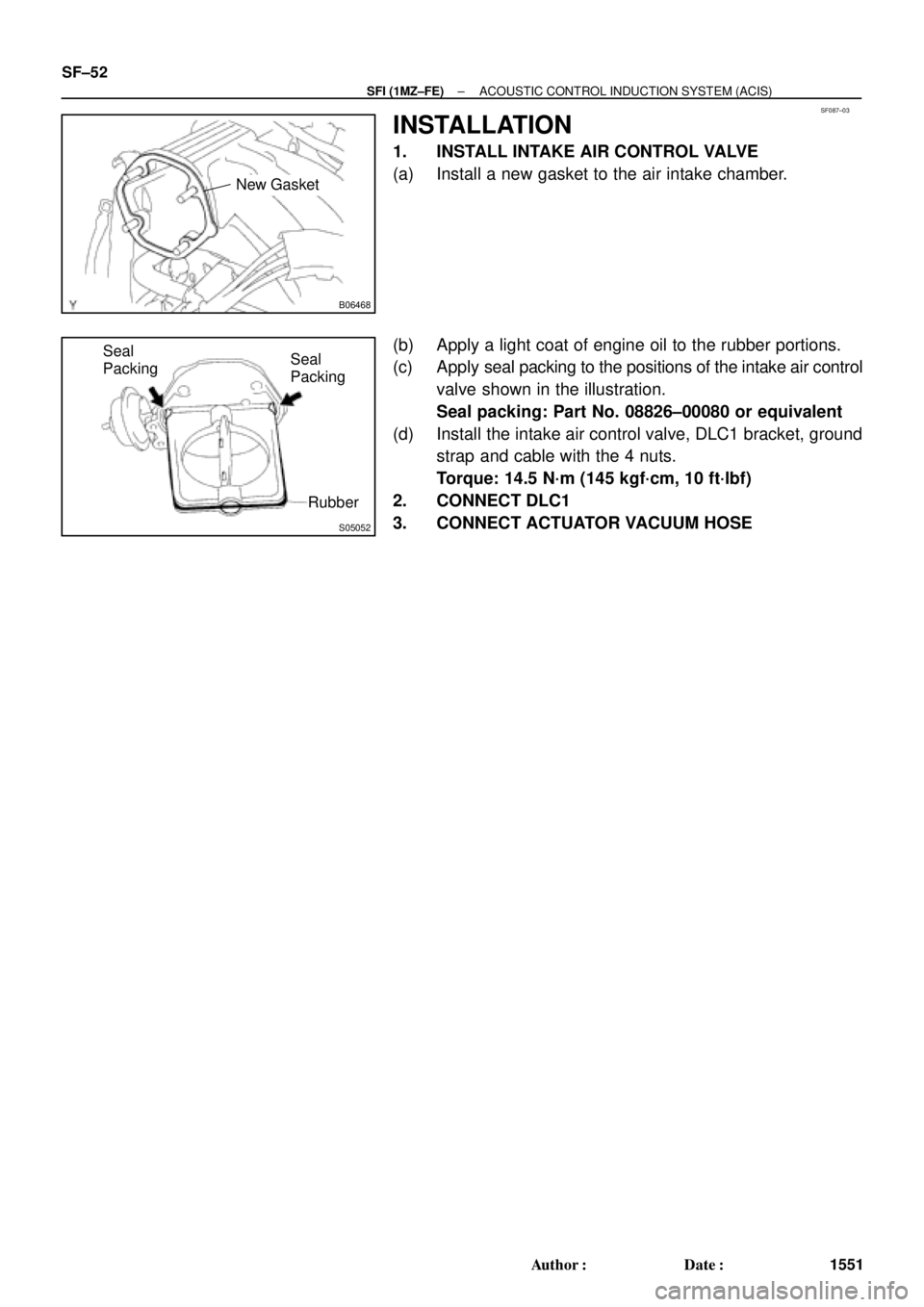
INSTALLATION
1. INSTALL INTAKE AIR CONTROL VALVE
(a) Install a new gasket to the air intake chamber.
(b) Apply a light coat of engine oil to the rubber portions.
(c) Apply seal packing to the positions of the intake air control
valve shown in the illustration.
Seal packing: Part No. 08826±00080 or equivalent
(d) Install the intake air control valve, DLC1 bracket, ground
strap and cable with the 4 nuts.
Torque: 14.5 N´m (145 kgf´cm, 10 ft´lbf)
2. CONNECT DLC1
3. CONNECT ACTUATOR VACUUM HOSE
Page 4163 of 4770
SF08I±03
S04759
ECT Switch19 mm
Deep Socket
Wrench
Gasket
S01196S01699Z17274
Ohmmeter
Resistance kW
Temperature °C (°F) Acceptable 30
20
10
5
3
2
1
0.5
0.3
0.2
0.1
40 ±20 0 20 60 80 100
(212) (176) (140) (104) (68) (32) (±4)
± SFI (1MZ±FE)ENGINE COOLANT TEMPERATURE (ECT) SENSOR
SF±63
1562 Author�: Date�:
ENGINE COOLANT
TEMPERATURE (ECT) SENSOR
INSPECTION
1. DRAIN ENGINE COOLANT
2. REMOVE ECT SENSOR
(a) Disconnect the ECT sensor connector.
(b) Using a 19 mm deep socket wrench, remove the ECT
sensor and gasket.
3. INSPECT ECT SENSOR
Using an ohmmeter, measure the resistance between the ter-
minals.
Resistance: Refer to the graph
If the resistance is not as specified, replace the ECT sensor.
4. REINSTALL ECT SENSOR
(a) Install a new gasket to the ECT sensor.
(b) Using a 19 mm deep socket, install the ECT sensor.
Torque: 20 N´m (200 kgf´cm, 14 ft´lbf)
(c) Connect the ECT sensor connector.
5. REFILL WITH ENGINE COOLANT
Page 4166 of 4770

SF08K±03
B06390
VSV Connector for
EVAP
Ground Cable
PCV Hose
Air Intake Chamber
Assembly
ECT Sensor
Connector ECT Sender
Gauge ConnectorEGR Valve Position
Sensor Connector
IAC Valve
Connector
VSV Connector
for EGR
VSV Connector for ACIS
Engine Wire
Engine Coolant
Reservoir HoseAir Assist Hose
Water Bypass Hose No.2 EGR Pipe
Throttle Position
Sensor Connector
No.1 Engine
HangerBrake Booster
Vacuum Hose Air Intake Chamber Stay
Water OutletPS Pressure Tube
�Gasket
19.5 (200, 14)
39 (400, 19)12 (120, 19)
15 (150, 11)
�Gasket
43 (440, 32)
Ground Starp
DLC1
�Gasket
15 (150, 11)
Grand Strap
Connector
�Gasket
39 (400, 29)
V±Bank Cover
Accelerator Cable
Throttle Cable
Air Cleaner
Hose
Purge HoseEGR Gas Temperature
Sensor Connector
Vacuum
HoseWater Bypass Hose
Fuel Inlet Hose
Heater Hose
Intake Manifold Assembly
Injector Connector x 9
Knock Sensor
Connector
Upper Radiator
Hose
Engine
Wire
Band
High±Tension Cord
Set �Gasket
: Specified torque
�Non±reusable partN´m (kgf´cm, ft´lbf)
�Retainer
Knock Sensor
SF±66
± SFI (1MZ±FE)KNOCK SENSOR
1565 Author�: Date�:
KNOCK SENSOR
COMPONENTS
Page 4167 of 4770
SF08L±03
P20115
SSTKnock Sensor 1
Knock Sensor 2
P01630
Ohmmeter
No Continuity
± SFI (1MZ±FE)KNOCK SENSOR
SF±67
1566 Author�: Date�:
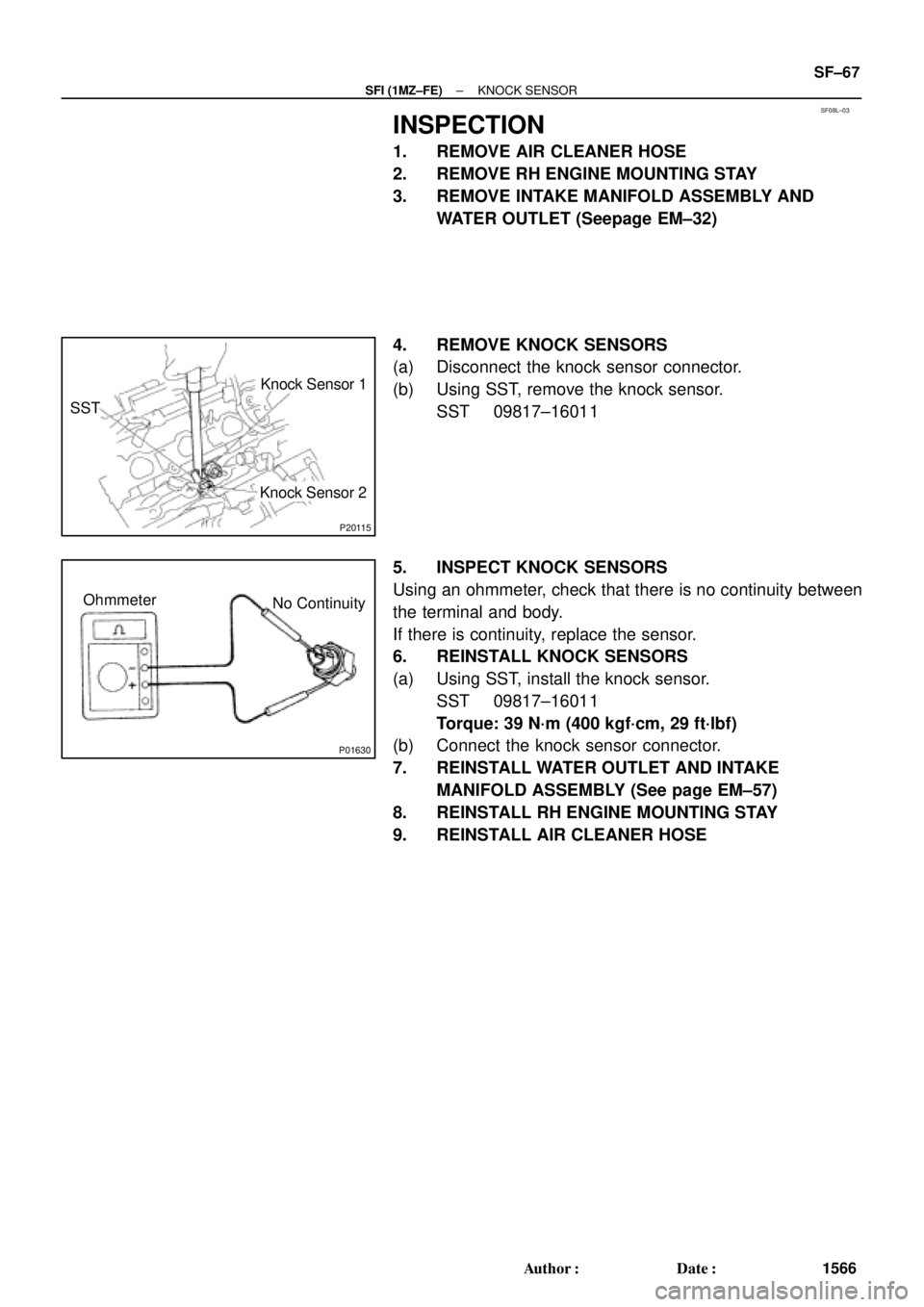
INSPECTION
1. REMOVE AIR CLEANER HOSE
2. REMOVE RH ENGINE MOUNTING STAY
3. REMOVE INTAKE MANIFOLD ASSEMBLY AND
WATER OUTLET (Seepage EM±32)
4. REMOVE KNOCK SENSORS
(a) Disconnect the knock sensor connector.
(b) Using SST, remove the knock sensor.
SST 09817±16011
5. INSPECT KNOCK SENSORS
Using an ohmmeter, check that there is no continuity between
the terminal and body.
If there is continuity, replace the sensor.
6. REINSTALL KNOCK SENSORS
(a) Using SST, install the knock sensor.
SST 09817±16011
Torque: 39 N´m (400 kgf´cm, 29 ft´lbf)
(b) Connect the knock sensor connector.
7. REINSTALL WATER OUTLET AND INTAKE
MANIFOLD ASSEMBLY (See page EM±57)
8. REINSTALL RH ENGINE MOUNTING STAY
9. REINSTALL AIR CLEANER HOSE
Page 4173 of 4770
SF08R±03
S05450
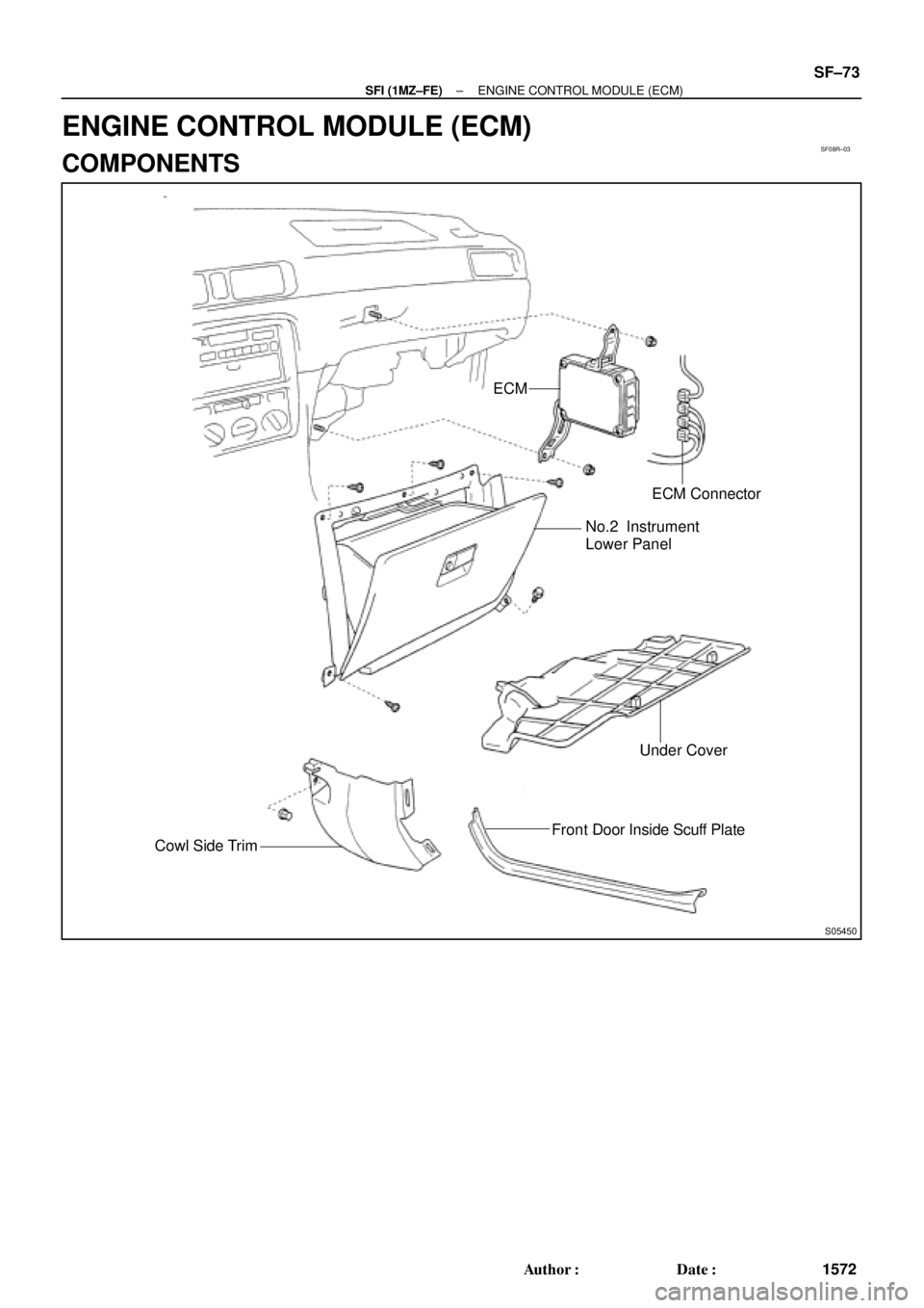
ECM
ECM Connector
No.2 Instrument
Lower Panel
Under Cover
Cowl Side TrimFront Door Inside Scuff Plate
± SFI (1MZ±FE)ENGINE CONTROL MODULE (ECM)
SF±73
1572 Author�: Date�:
ENGINE CONTROL MODULE (ECM)
COMPONENTS
Page 4174 of 4770
SF08S±01
SF±74
± SFI (1MZ±FE)ENGINE CONTROL MODULE (ECM)
1573 Author�: Date�:
INSPECTION
1. REMOVE ECM
2. INSPECT ECM (See page DI±218)
3. REINSTALL ECM
Page 4175 of 4770
FUEL CUT RPM
SF±75
1574 Author�: Date�:
F")
S04528
5 mm
Hexagon
Wrench
Clip
SF08T±03
S05358
TOYOTA
Hand±Held Tester
B00623
Sound Scope
Sound Scope California A/T
Except California A/T
± SFI (1MZ±FE)FUEL CUT RPM
SF±75
1574 Author�: Date�:
FUEL CUT RPM
INSPECTION
1. REMOVE V±BANK COVER
(a) Using a 5 mm hexagon wrench, remove the 2 cap nuts.
(b) Disconnect the 2 clips, and remove the V±bank cover.
2. WARM UP ENGINE
Allow the engine to warm up to normal operating temperature.
3. CONNECT TOYOTA HAND±HELD TESTER OR OBDII
SCAN TOOL
(a) Connect the TOYOTA hand±held tester or OBDII scan
tool to the DLC3.
(b) Please refer to the TOYOTA hand±held tester or OBDII
scan tool operator's manual for further details.
4. INSPECT FUEL CUT OFF PRM
(a) Increase the engine speed to at least 3,500 rpm.
(b) Use a sound scope to check for injector operating noise.
(c) Check that when the throttle lever is released, injector op-
eration noise stops momentarily and then resumes.
HINT:
Measure with the A/C OFF.
Fuel return rpm: 1,200 rpm
5. DISCONNECT TOYOTA HAND±HELD TESTER OR
OBDII SCAN TOOL
6. REINSTALL V±BANK COVER
HINT:
For fixing the V±bank cover, push on the cover until a ºclickº is
felt.
Page 4293 of 4770
 Visually check the belt for excessive w")
P06717
SR06D±01
Z00038
DENSO Borroughs
P06723
CORRECT WRONG WRONG
± STEERINGDRIVE BELT
SR±3
2098 Author�: Date�:
DRIVE BELT
INSPECTION
INSPECT DRIVE BELT
(a) Visually check the belt for excessive wear, frayed cords
etc.
If any defect has been found, replace the drive belt.
HINT:
Cracks on the rib side of a belt are considered acceptable. If the
belt has chunks missing from the ribs, it should be replaced.
(b) Using a belt tension gauge, measure the belt tension.
Belt tension gauge:
DENSO BTG±20 (95506±00020)
Borroughs No. BT±33±73F
5S±FE Engine:
Drive belt tension:
New belt: 95 ± 145 lbf
Used belt: 60 ± 100 lbf
1MZ±FE Engine:
Drive belt tension:
New belt: 150 ± 185 lbf
Used belt: 95 ± 135 lbf
If the belt tension is not as specified, adjust it.
HINT:
�ºNew beltº refers to a belt which has been used less than
5 minutes on a running engine.
�ºUsed beltº refers to a belt which has been used on a run-
ning engine for 5 minutes or more.
�After installing a belt, check that it fits properly in the
ribbed grooves.
�Check with your hand to confirm that the belt has not
slipped out of the groove on the bottom of the pulley.
�After installing a new belt, run the engine for about 5 min-
utes and recheck the belt tension.
 Acceptable 30
20
10
5
3
2
1
0.5
0.3
0.2
0.1
40 ±20 0 20 60 80 100
(212) (176")