Page 3428 of 4770
CYLINDER HEAD
1208 Author�: Date�:
(f) Remove the 6 bolts, 2 nuts, intake manifold and gasket.
15. California:
REMOVE AIR HOSE FOR AIR ASSIST S")
A07359
S06000
S05962
EM±36
± ENGINE MECHANICAL (5S±FE)CYLINDER HEAD
1208 Author�: Date�:
(f) Remove the 6 bolts, 2 nuts, intake manifold and gasket.
15. California:
REMOVE AIR HOSE FOR AIR ASSIST SYSTEM
Disconnect the air hose from the cylinder head port, and re-
move the air hose.
16. REMOVE DELIVERY PIPE AND INJECTORS
(a) Disconnect the 4 injector connectors.
(b) Remove the 2 bolts and delivery pipe together with the 4
injectors.
NOTICE:
Be careful not to drop the injectors when removing the de-
livery pipe.
(c) Remove the 4 insulators (except California) and 2
spacers from the cylinder head.
(d) Pull out the 4 injectors from the delivery pipe.
(e) California:
Remove the 2 O±rings, insulator and grommet from each
injector.
(f) Except California:
Remove the O±ring and grommet from each injector.
17. DISCONNECT TIMING BELT FROM CAMSHAFT TIM-
ING PULLEY (See page EM±17)
18. REMOVE CAMSHAFT TIMING PULLEY
(See page EM±17)
19. REMOVE NO.1 IDLER PULLEY AND TENSION
SPRING
Remove the bolt, pulley and tension spring.
20. REMOVE NO.3 TIMING BELT COVER
Remove the 3 bolts and timing and cover.
Page 3429 of 4770
CYLINDER HEAD
EM±37
1209 Author�: Date�:
NOTICE:
�Support the timing belt, so the meshing of the crank-
shaft timing pulley and")
A02593
S05933
P03355
10 ± 45°
Knock
Pin
± ENGINE MECHANICAL (5S±FE)CYLINDER HEAD
EM±37
1209 Author�: Date�:
NOTICE:
�Support the timing belt, so the meshing of the crank-
shaft timing pulley and timing belt does not shift.
�Be careful not to drop anything inside the timing belt
cover.
�Do not allow the belt to come into contact with oil, wa-
ter or dust.
21. REMOVE ENGINE HANGERS AND GENERATOR
BRACKET
(a) Remove the 3 bolts, the generator bracket and RH engine
hanger assembly.
(b) Remove the bolt and LH engine hanger.
22. REMOVE OIL PRESSURE SWITCH
23. REMOVE CYLINDER HEAD COVER
Remove the 4 nuts, grommets, head cover and gasket.
HINT:
Arrange the grommets in the correct order, so that they can be
reinstalled into their original positions. This minimizes any pos-
sibility of oil leakage due to reuse of the grommets in different
positions.
24. REMOVE CAMSHAFTS
NOTICE:
Since the thrust clearance of the camshaft is small, the
camshaft must be kept level while it is being removed. If the
camshaft is not kept level, the portion of the cylinder head
receiving the shaft thrust may crack or be damaged, caus-
ing the camshaft to seize or break. To avoid this, the follow-
ing steps should be carried out.
(a) Remove the exhaust camshaft.
(1) Set the knock pin of the intake camshaft at 10 ± 45°
BTDC of camshaft angle.
HINT:
The above angle allows No.2 and No.4 cylinder cam lobes of
the exhaust camshaft to push their valve lifters evenly.
Page 3448 of 4770
CYLINDER HEAD
1228 Author�: Date�:
(b) Install the exhaust c")
P03281
10 ± 45°
Knock
Pin
P03373
Assembly
Reference Mark
Timing
Mark
P03374
P03375
1 2
3 410
5 6
8
79 EM±56
± ENGINE MECHANICAL (5S±FE)CYLINDER HEAD
1228 Author�: Date�:
(b) Install the exhaust camshaft.
(1) Set the knock pin of the intake camshaft at 10 ± 45°
BTDC of camshaft angle.
HINT:
The above angle allows the No.2 and No.4 cylinder cam lobes
of the exhaust camshaft to push their valve lifters evenly.
(2) Apply MP grease to the thrust portion of the cam-
shaft.
(3) Engage the exhaust camshaft gear to the intake
camshaft gear by matching the timing marks on
each gear.
(4) Roll down the exhaust camshaft onto the bearing
journals while engaging gears with each other.
NOTICE:
There are also assembly reference marks on each gear as
shown in the illustration. Do not use these marks.
(5) Turn the intake camshaft clockwise or counterclock-
wise a little until the exhaust camshaft sits in the
bearing journals evenly without rocking the cam-
shaft on the bearing journals.
NOTICE:
It is very important to replace the camshaft in the bearing
journals evenly while tightening bearing caps in the subse-
quent steps.
(6) Install the bearing caps in their proper locations.
(7) Apply a light coat of engine oil on the threads and
under the heads of the bearing cap bolts.
(8) Install and uniformly tighten the 10 bearing cap
bolts in several passes, in the sequence shown.
Torque: 19 N´m (190 kgf´cm, 14 ft´lbf)
Page 3450 of 4770
CYLINDER HEAD
1230 Author�: Date�:")
P13638
Adhesive
S05962
Z09141
California
Except California New O±RingNew Insulator
New GrommetNew O±Ring
New GrommetNew
O±Ring EM±58
± ENGINE MECHANICAL (5S±FE)CYLINDER HEAD
1230 Author�: Date�:
9. INSTALL OIL PRESSURE SWITCH
(a) Apply adhesive to 2 or 3 threads.
Adhesive:
Part No. 08833±00080, THREE BOND 1324 or equiva-
lent
(b) Install the oil pressure switch.
10. INSTALL ENGINE HANGERS AND GENERATOR
BRACKET
(a) Install the generator bracket and RH engine hanger as-
sembly with the 3 bolts.
Torque: 42 N´m (425 kgf´cm, 31 ft´lbf)
(b) Install the LH engine hanger with the bolt.
Torque: 25 N´m (250 kgf´cm, 18 ft´lbf)
11. INSTALL NO.3 TIMING BELT COVER
Install the timing belt cover with the 3 bolts.
Torque: 7.8 N´m (80 kgf´cm, 69 in.´lbf)
12. TEMPORARILY INSTALL NO.1 IDLER PULLEY AND
TENSION SPRING (See page EM±23)
13. INSTALL CAMSHAFT TIMING PULLEY
(See page EM±23)
14. CONNECT TIMING BELT TO CAMSHAFT TIMING
PULLEY (See page EM±23)
15. INSTALL INJECTORS AND DELIVERY PIPE
(a) California:
Install a new insulator and grommet to each injector.
(b) Except California:
Install a new grommet to each injector.
(c) California:
Apply a light coat of gasoline onto 2 new O±rings, and
install them to each injector.
(d) Except California:
Apply a light coat of gasoline onto a new O±ring, and
install it to each injector.
Page 3474 of 4770
EM08H±03
A07366
No.2 Timing Belt
Cover
No.1 Timing Belt
Cover
Crankshaft
Pulley
No.2 Idler PulleyTension Spring* Gasket
Timing Belt Guide Timing Belt
High±Tension Cord
Spark Plug
N´m (kgf´cm, ft´lbf)Wire
ClampGenerator
Wire Clamp
Crankshaft Timing Pulley
Camshaft Timing Pulley
No.1 Idler PulleyWire ClampWire Clamp
108 (1,100, 80)
54 (550, 40)
42 (425, 31)
18 (180, 13)
42 (425, 31)
: Specified torque* Gasket
* Replace only if damaged
EM±82
± ENGINE MECHANICAL (5S±FE)CYLINDER BLOCK
1254 Author�: Date�:
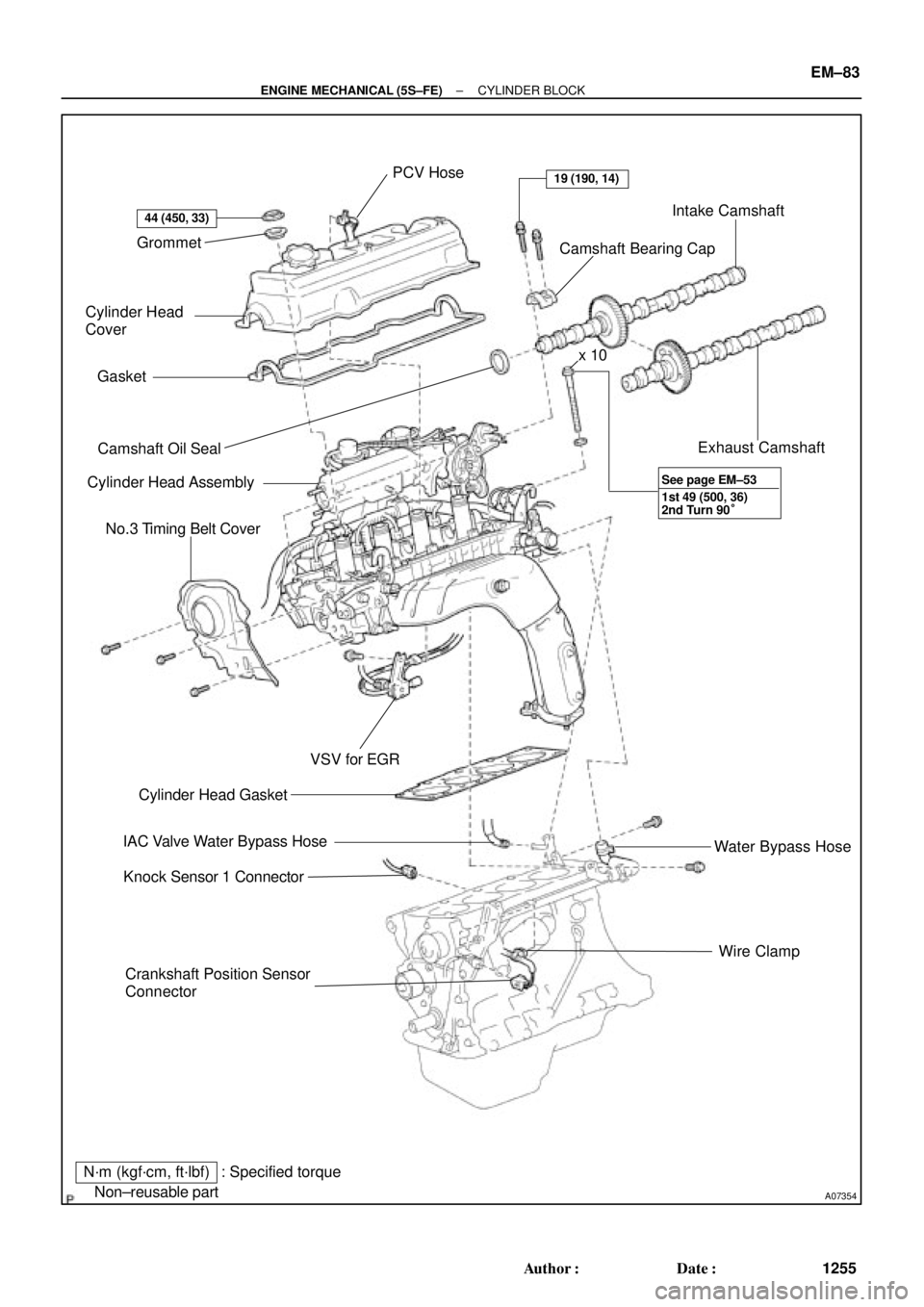
CYLINDER BLOCK
COMPONENTS
Page 3475 of 4770
A07354
Grommet
Cylinder Head
Cover
Gasket
� Camshaft Oil Seal
Cylinder Head Assembly
No.3 Timing Belt Cover
Crankshaft Position Sensor
ConnectorWire Clamp Water Bypass Hose Exhaust Camshaft Intake Camshaft
Camshaft Bearing Cap PCV Hose
� Cylinder Head Gasket
IAC Valve Water Bypass Hose
Knock Sensor 1 Connector
N´m (kgf´cm, ft´lbf)
� Non±reusable part
44 (450, 33)
19 (190, 14)
VSV for EGR
: Specified torquex 10
1st 49 (500, 36)
2nd Turn 90° See page EM±53
± ENGINE MECHANICAL (5S±FE)CYLINDER BLOCK
EM±83
1255 Author�: Date�:
Page 3478 of 4770
CYLINDER BLOCK
1258 Author�: Date�:
DISASSEMBLY
1. INSTALL ENGINE TO ENGINE STAND FOR DIS-
ASSEMBLY
2. REMOVE TIMING BELT AND PULLEYS
(See pa")
EM0YW±01
S06011
1
3
2 EM±86
± ENGINE MECHANICAL (5S±FE)CYLINDER BLOCK
1258 Author�: Date�:
DISASSEMBLY
1. INSTALL ENGINE TO ENGINE STAND FOR DIS-
ASSEMBLY
2. REMOVE TIMING BELT AND PULLEYS
(See page EM±17)
3. REMOVE CYLINDER HEAD ASSEMBLY
(a) Remove the 3 bolts and No.3 timing belt cover.
(b) Remove the cylinder head cover.
(1) Disconnect the PCV hose from the intake manifold.
(2) Remove the 4 nuts, 4 grommets, head cover and
gasket.
(c) Remove the camshafts. (See page EM±33)
(d) Disconnect the knock sensor 1 connector.
(e) Disconnect the crankshaft position sensor connector.
(f) Disconnect the wire clamp from the generator drive belt
adjusting bar.
(g) Disconnect the IAC valve water bypass hose from the wa-
ter bypass pipe.
(h) Disconnect the water bypass hose (from the water by-
pass pipe) from the water outlet.
(i) Remove the bolt holding the VSV for EGR to the intake
manifold.
(j) Remove the 2 bolts holding the water bypass pipe to the
cylinder head.
(k) Remove the cylinder head assembly.
(See page EM±33)
4. REMOVE OIL DIPSTICK
5. REMOVE OIL PAN AND OIL PUMP
(a) Disconnect the crankshaft position sensor connector
from the generator drive belt adjusting bar.
(b) Remove the oil pan and oil pump. (See page LU±7)
6. REMOVE PS PUMP BRACKET
Remove the 3 bolts and pump bracket.
7. REMOVE KNOCK SENSOR 1 (See page SF±57)
8. REMOVE OIL FILTER (See page LU±2)
9. REMOVE WATER PUMP, WATER BYPASS PIPE AND
OIL COOLER (w/ OIL COOLER) ASSEMBLY
(a) w/ Oil Cooler:
Remove the nut and union bolt, and disconnect the oil
cooler. Remove the O±ring.
(b) Remove the bolt and generator drive belt adjusting bar.
(c) Remove the 3 bolts in the sequence shown, remove the
water pump, water bypass pipe, oil cooler (w/ oil cooler)
assembly and O±ring.
Page 3505 of 4770
± ENGINE MECHANICAL (5S±FE)CYLINDER BLOCK
EM±113
1285 Author�: Date�:
(f) Install the wire clamp to the generator drive belt adjusting
bar.
(g) Connect the IAC valve water bypass hose to the water by-
pass pipe.
(h) Connect the water bypass hose (from the water bypass
pipe) to the water outlet.
(i) Install the camshafts. (See page EM±53)
(j) Install the cylinder head cover.
(1) Install the cylinder head cover. (See page EM±53)
(2) Connect the PCV hose to the intake manifold.
(k) Install the No.3 timing belt cover with the 3 bolts.
Torque: 7.8 N´m (80 kgf´cm, 69 in.´lbf)
23. INSTALL TIMING BELT AND PULLEYS
(See page EM±23)
24. DISCONNECT ENGINE FROM ENGINE STAND