Page 2624 of 4770

A00209
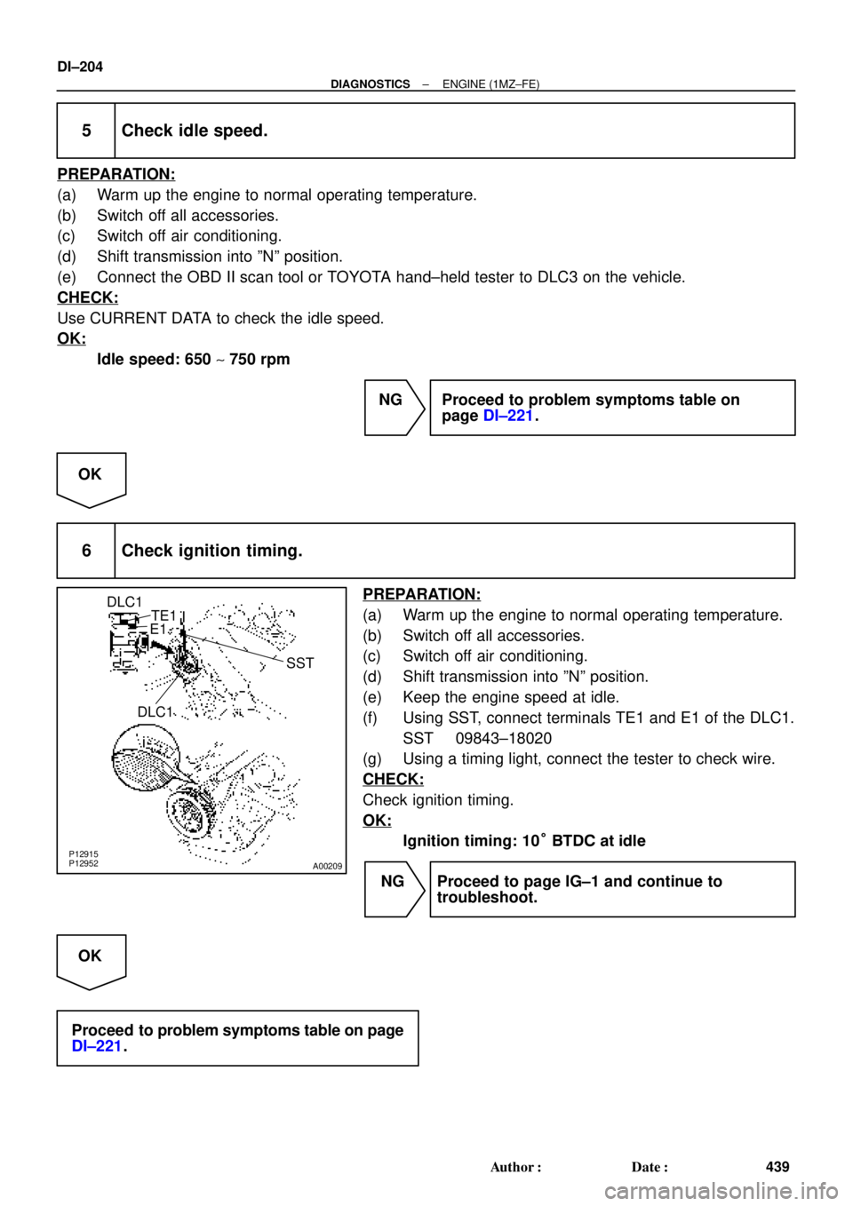
DLC1
TE1
E1
SST
DLC1
P12915
P12952
DI±204
± DIAGNOSTICSENGINE (1MZ±FE)
439 Author�: Date�:
5 Check idle speed.
PREPARATION:
(a) Warm up the engine to normal operating temperature.
(b) Switch off all accessories.
(c) Switch off air conditioning.
(d) Shift transmission into ºNº position.
(e) Connect the OBD II scan tool or TOYOTA hand±held tester to DLC3 on the vehicle.
CHECK:
Use CURRENT DATA to check the idle speed.
OK:
Idle speed: 650 ~ 750 rpm
NG Proceed to problem symptoms table on
page DI±221.
OK
6 Check ignition timing.
PREPARATION:
(a) Warm up the engine to normal operating temperature.
(b) Switch off all accessories.
(c) Switch off air conditioning.
(d) Shift transmission into ºNº position.
(e) Keep the engine speed at idle.
(f) Using SST, connect terminals TE1 and E1 of the DLC1.
SST 09843±18020
(g) Using a timing light, connect the tester to check wire.
CHECK:
Check ignition timing.
OK:
Ignition timing: 10° BTDC at idle
NG Proceed to page IG±1 and continue to
troubleshoot.
OK
Proceed to problem symptoms table on page
DI±221.
Page 2627 of 4770

± DIAGNOSTICSENGINE (1MZ±FE)
DI±207
442 Author�: Date�:
7. ENGINE OPERATING CONDITION
NOTICE:
The values given below for ºNormal Conditionº are representative values, so a vehicle may still be
normal even if its value varies from those listed here. So do not decide whether a part is faulty or
not solely according to the ºNormal Conditionº here.
(a) CARB mandated signals.
TOYOTA hand±held tester displayMeasurement ItemNormal Condition*
FUEL SYS #1
Fuel System Bank 1
OPEN: Air±fuel ratio feedback stopped
CLOSED: Air±fuel ratio feedback operating
Idling after warming up: CLOSED
FUEL SYS #2
Fuel System Bank 2
OPEN: Air±fuel ratio feedback stopped
CLOSED: Air±fuel ratio feedback operating
Idling after warming up: CLOSED
CALC LOAD
Calculator Load:
Current intake air volume as a proportion of max.
intake air volumeIdling: 13.1 ~ 18.7%
Racing without load (2,500rpm): 11.7 ~ 17.3%
COOLANT TEMP.Engine Coolant Temp. Sensor ValueAfter warming up: 80 ~ 95°C (176 ~ 203°F)
SHORT FT #1Short±term Fuel Trim Bank 10 ± 20%
LONG FT #1Long±term Fuel Trim Bank 10 ± 20%
SHORT FT #2Short±term Fuel Trim Bank 20 ± 20%
LONG FT #2Long±term Fuel Trim Bank 20 ± 20%
ENGINE SPDEngine SpeedIdling: 650 ~ 750 rpm
VEHICLE SPDVehicle SpeedVehicle stopped: 0 km/h (0 mph)
IGN ADVANCEIgnition Advance:
Ignition Timing of Cylinder No. 1Idling: BTDC 10 ~ 25.0°
INTAKE AIRIntake Air Temp. Sensor ValueEquivalent to Ambient Temp.
MAFAir Flow Rate Through Mass Air Flow Meter
Idling: 3.3 ~ 4.7 gm/sec.
Racing without load (2,500 rpm):
10.4 ~ 15.4 gm/sec.
THROTTLE POS
Voltage Output of Throttle Position Sensor
Calculated as a percentage:
0 V "0%, 5 V "100%Throttle valve fully closed: 7 ~ 11 %
Throttle valve fully open: 65 ~ 75%
*: If no conditions are specifically stated for ºldlingº, it means the shift lever is at N or P position, the A/C switch
is OFF and all accessory switches are OFF.
Page 2633 of 4770

± DIAGNOSTICSENGINE (1MZ±FE)
DI±213
448 Author�: Date�:
DTC No.
(See Page)Detection ItemTrouble AreaMILMemory
P0300
(DI±276)Random/Multiple Cylinder
Misfire Detected�Ignition system
�Injector
�Fuel line pressure
EGR
P0301
P0302
P0303
P0304
P0305
P0306
(DI±276)Misfire Detected
± Cylinder 1
± Cylinder 2
± Cylinder 3
± Cylinder 4
± Cylinder 5
± Cylinder 6
�EGR
�Compression pressure
�Valve clearance not to specification
�Valve timing
�Mass air flow meter
�Engine coolant temp. sensor
�Open or short engine wire
�Connector connection
�ECM
�*2�
P0325
(DI±283)Knock Sensor 1 Circuit
Malfunction�Open or short in knock sensor 1 circuit
�Knock sensor 1 (looseness)
�ECM
�*1�
P0330
(DI±283)Knock Sensor 2 Circuit
Malfunction�Open or short in knock sensor 2 circuit
�Knock sensor 2 (looseness)
�ECM
�*1�
P0335
(DI±287)Crankshaft Position Sensor
ºAº Circuit Malfunction
�Open or short in crankshaft position sensor circuit
�Crankshaft position sensor
�Starter
�ECM
�*1�
P0340
(DI±290)Camshaft Position Sensor
Circuit Malfunction
�Open or short in camshaft position sensor circuit
�Camshaft position sensor
�Starter
�ECM
�*1�
P0401
(DI±292)Exhaust Gas Recirculation
Flow Insufficient Detected
�EGR valve (stuck closed)
�Open or short in EGR gas temp. sensor circuit
�EGR gas temp. sensor
�Open in VSV circuit for EGR
�VSV for EGR
�Vacuum control valve
�Vacuum hose disconnected or blocked
�ECM
�*1�
P0402
(DI±302)Exhaust Gas Recirculation
Flow Excessive Detected
�EGR valve stuck open
�VSV for EGR open malfunction
�Short in VSV circuit for EGR
�Open or short in EGR valve position sensor circuit
�EGR valve position sensor
�ECM
�*1�
*3
P0420
(DI±305)Catalyst System Efficiency
Below Threshold
(Except California Spec.)�Three±way catalytic converter
�Open or short in heated oxygen sensor circuit
�Heated oxygen sensor
�*2�
*4
P0420
(DI±308)Catalyst System Efficiency
Below Threshold
(Only for California Spec.)
�Three±way catalytic converter
�Open or short in heated oxygen sensor (bank 1, sensor 2)
circuit
�Heated oxygen sensor (bank 1, sensor 2)
�Open or short in A/F sensor (bank 1, 2 sensor 1) circuit
�A/F sensor (bank 1, 2 sensor 1)
�*2�
*1: MIL lights up
*2: MIL lights up on U.S.A and Canadian specification vehicles
*3: Except California specification vehicles
*4: Only for California specification vehicle
Page 2642 of 4770

DI07F±06
A00435
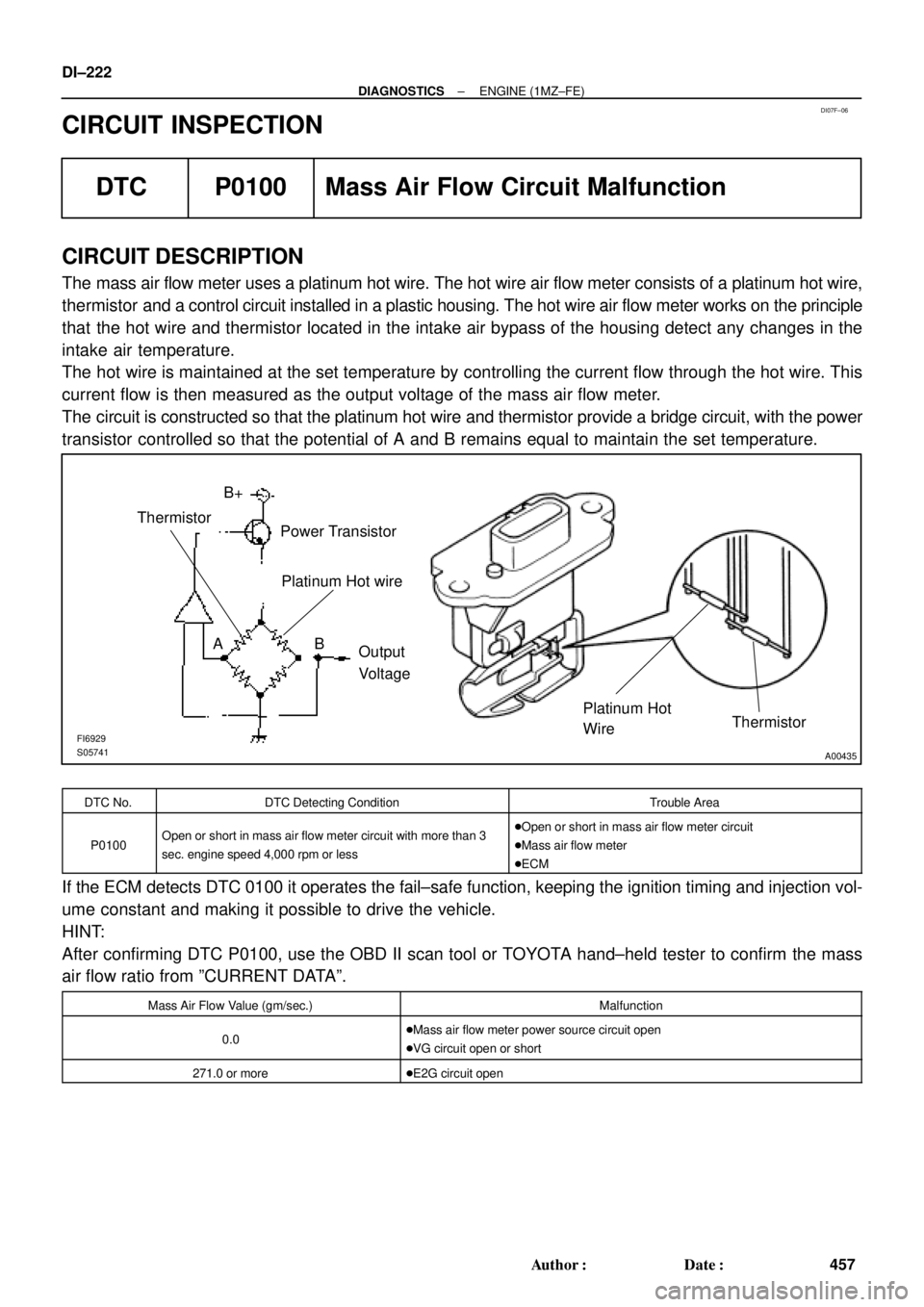
B+
Thermistor
Power Transistor
Platinum Hot wire
B
Output
Platinum Hot
Wire A
Voltage
Thermistor
FI6929
S05741
DI±222
± DIAGNOSTICSENGINE (1MZ±FE)
457 Author�: Date�:
CIRCUIT INSPECTION
DTC P0100 Mass Air Flow Circuit Malfunction
CIRCUIT DESCRIPTION
The mass air flow meter uses a platinum hot wire. The hot wire air flow meter consists of a platinum hot wire,
thermistor and a control circuit installed in a plastic housing. The hot wire air flow meter works on the principle
that the hot wire and thermistor located in the intake air bypass of the housing detect any changes in the
intake air temperature.
The hot wire is maintained at the set temperature by controlling the current flow through the hot wire. This
current flow is then measured as the output voltage of the mass air flow meter.
The circuit is constructed so that the platinum hot wire and thermistor provide a bridge circuit, with the power
transistor controlled so that the potential of A and B remains equal to maintain the set temperature.
DTC No.DTC Detecting ConditionTrouble Area
P0100Open or short in mass air flow meter circuit with more than 3
sec. engine speed 4,000 rpm or less�Open or short in mass air flow meter circuit
�Mass air flow meter
�ECM
If the ECM detects DTC 0100 it operates the fail±safe function, keeping the ignition timing and injection vol-
ume constant and making it possible to drive the vehicle.
HINT:
After confirming DTC P0100, use the OBD II scan tool or TOYOTA hand±held tester to confirm the mass
air flow ratio from ºCURRENT DATAº.
Mass Air Flow Value (gm/sec.)Malfunction
0.0�Mass air flow meter power source circuit open
�VG circuit open or short
271.0 or more�E2G circuit open
Page 2696 of 4770

DI±276
± DIAGNOSTICSENGINE (1MZ±FE)
511 Author�: Date�:
DTC P0300 Random/Multiple Cylinder Misfire Detected
DTC P0301 Cylinder 1 Misfire Detected
DTC P0302 Cylinder 2 Misfire Detected
DTC P0303 Cylinder 3 Misfire Detected
DTC P0304 Cylinder 4 Misfire Detected
DTC P0305 Cylinder 5 Misfire Detected
DTC P0306 Cylinder 6 Misfire Detected
CIRCUIT DESCRIPTION
Misfire: The ECM uses the crankshaft position sensor and camshaft position sensor to monitor changes in
the crankshaft rotation for each cylinder.
The ECM counts the number of times the engine speed change rate indicates that misfire has occurred.
When the misfire rate equals or exceeds the count indicating that the engine condition has deteriorated, the
MIL lights up.
If the misfire rate is high enough and the driving conditions will cause catalyst overheating, the MIL blinks
when misfiring occurs.
DTC No.DTC Detecting ConditionTrouble Area
P0300Misfiring of random cylinders is detected during any
particular 200 or 1,000 revolutions�Ignition system
�Injector
�Fuel line pressure
P0301
P0302
P0303For any particular 200 revolutions for engine, misfiring is de-
tected which can cause catalyst overheating
(This causes MIL to blink)
�EGR
�Compression pressure
�Valve clearance not to specification
�Valve timing
�Mass air flow meterP0303
P0304
P0305
P0306For any particular 1,000 revolutions of engine, misfiring is de-
tected which causes a deterioration in emission
(2 trip detection logic)
�Mass air flow meter
�Engine coolant temp. sensor
�Open or short in engine wire
�Connector connection
�ECM
DI07S±07
Page 2702 of 4770
DI±282
± DIAGNOSTICSENGINE (1MZ±FE)
517 Author�: Date�:
8 Check mass air flow meter and engine coolant temp. sensor
(See pages SF±35, SF±63).
NG Repair or replace.
OK
Check compression pressure, valve
clearance and valve timing.
Page 2703 of 4770

A03315
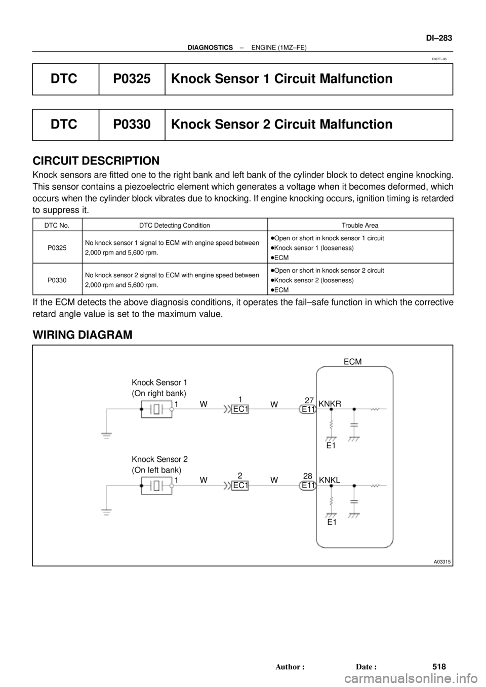
Knock Sensor 1
(On right bank)
Knock Sensor 2
(On left bank)EC1 1W
W1
2W
WECM
KNKR
KNKLE1
E1 EC1 1E11
E112827
± DIAGNOSTICSENGINE (1MZ±FE)
DI±283
518 Author�: Date�:
DTC P0325 Knock Sensor 1 Circuit Malfunction
DTC P0330 Knock Sensor 2 Circuit Malfunction
CIRCUIT DESCRIPTION
Knock sensors are fitted one to the right bank and left bank of the cylinder block to detect engine knocking.
This sensor contains a piezoelectric element which generates a voltage when it becomes deformed, which
occurs when the cylinder block vibrates due to knocking. If engine knocking occurs, ignition timing is retarded
to suppress it.
DTC No.DTC Detecting ConditionTrouble Area
P0325No knock sensor 1 signal to ECM with engine speed between
2,000 rpm and 5,600 rpm.�Open or short in knock sensor 1 circuit
�Knock sensor 1 (looseness)
�ECM
P0330No knock sensor 2 signal to ECM with engine speed between
2,000 rpm and 5,600 rpm.�Open or short in knock sensor 2 circuit
�Knock sensor 2 (looseness)
�ECM
If the ECM detects the above diagnosis conditions, it operates the fail±safe function in which the corrective
retard angle value is set to the maximum value.
WIRING DIAGRAM
DI07T±06
Page 2709 of 4770
± DIAGNOSTICSENGINE (1MZ±FE)
DI±289
524 Author�: Date�:
3 Inspect sensor installation and teeth of crankshaft timing pulley.
NG Tighten the sensor.
Replace crankshaft timing pulley.
OK
Check and replace ECM
(See page IN±31).