Page 3402 of 4770
IDLE SPEED
1182 Author�: Date�:
IDLE SPEED
INSPECTION
1. INITIAL CONDITIONS
(a) Engine at normal operating temperature
(b) Air cleaner installed
(c")
EM081±05
S05331
EM±10
± ENGINE MECHANICAL (5S±FE)IDLE SPEED
1182 Author�: Date�:
IDLE SPEED
INSPECTION
1. INITIAL CONDITIONS
(a) Engine at normal operating temperature
(b) Air cleaner installed
(c) All pipes and hoses of air induction system connected
(d) All vacuum lines properly connected
(e) SFI system wiring connectors fully plugged
(f) All operating accessories switched OFF
(g) Ignition timing check correctly
(h) Transmission in neutral position
(i) Air conditioning switched OFF
2. CONNECT TOYOTA HAND±HELD TESTER OR OBDII
SCAN TOOL
(a) Remove the fuse cover on the instrument panel.
(b) Connect a TOYOTA hand±held tester or OBDII scan tool
to the DLC3.
(c) Please refer to the TOYOTA hand±held tester or OBDII
scan tool operator's manual for further details.
3. INSPECT IDLE SPEED
(a) Race the engine at 2,500 rpm for approx. 90 seconds.
(b) Check the idle speed.
Idle speed (w/ Cooling fan OFF): 700 ± 50 rpm
If the idle speed is not as specified, check the IAC valve and air
intake system.
4. DISCONNECT TOYOTA HAND±HELD TESTER OR
OBDII SCAN TOOL
Page 3407 of 4770
EM083±03
S05284
Engine Moving Control Rod
No.2 RH Engine Mounting Bracket
Generator Drive Belt
RH Front Fender Apron SealPS Pump Drive BeltGround Strap Connector
N´m (kgf´cm, ft´lbf)
52 (530, 38)64 (650, 47)
64 (650, 47)
: Specified torque
± ENGINE MECHANICAL (5S±FE)TIMING BELT
EM±15
1187 Author�: Date�:
TIMING BELT
COMPONENTS
Page 3408 of 4770
S05937
No.2 Timing Belt
Cover
No.1 Timing Belt
Cover
Tension Spring Crankshaft
Pulley
Camshaft Timing Pulley
No.1 Idler Pulley
No.2 Idler Pulley
Oil Pump Pulley
Crankshaft Timing Pulley Wire ClampWire ClampWire ClampSpark Plug High±Tension CordTiming Belt Guide Timing Belt
*
1 Gasket Wire
ClampGenerator Wire
Generator Connector
Generator
Wire
Clamp
N´m (kgf´cm, ft´lbf)
*
2 For use with SST
42 (425, 31)
42 (425, 31)
24 (245, 18)18 (180, 13) 108 (1,100, 80)
54 (550, 40)
*
2
37 (380, 27)
: Specified torque*
1 Gasket
*
1
Replace only if damaged EM±16
± ENGINE MECHANICAL (5S±FE)TIMING BELT
1188 Author�: Date�:
Page 3409 of 4770
EM084±04
S05609
S05249
S05296
S05597
± ENGINE MECHANICAL (5S±FE)TIMING BELT
EM±17
1189 Author�: Date�:
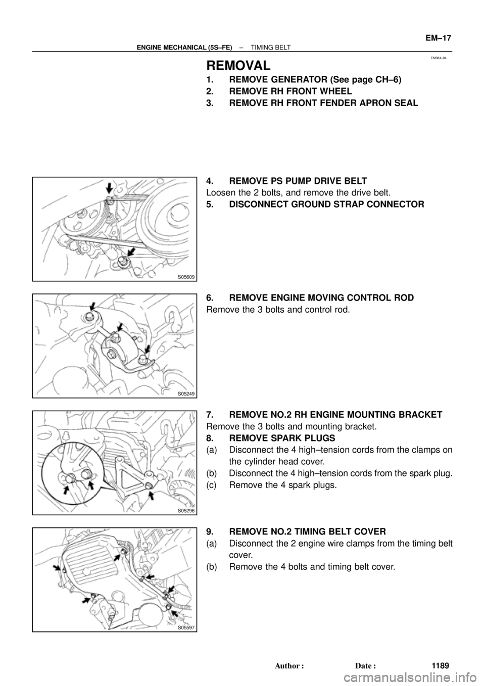
REMOVAL
1. REMOVE GENERATOR (See page CH±6)
2. REMOVE RH FRONT WHEEL
3. REMOVE RH FRONT FENDER APRON SEAL
4. REMOVE PS PUMP DRIVE BELT
Loosen the 2 bolts, and remove the drive belt.
5. DISCONNECT GROUND STRAP CONNECTOR
6. REMOVE ENGINE MOVING CONTROL ROD
Remove the 3 bolts and control rod.
7. REMOVE NO.2 RH ENGINE MOUNTING BRACKET
Remove the 3 bolts and mounting bracket.
8. REMOVE SPARK PLUGS
(a) Disconnect the 4 high±tension cords from the clamps on
the cylinder head cover.
(b) Disconnect the 4 high±tension cords from the spark plug.
(c) Remove the 4 spark plugs.
9. REMOVE NO.2 TIMING BELT COVER
(a) Disconnect the 2 engine wire clamps from the timing belt
cover.
(b) Remove the 4 bolts and timing belt cover.
Page 3410 of 4770
TIMING BELT
1190 Author�: Date�:
10. SET NO.1 CYLINDER TO TDC/COMPRESSION
(a) Turn the crankshaft pulley, an")
S05587
Turn
S05580
A02585
S05583
Pry
Move
S05593
SSTSST EM±18
± ENGINE MECHANICAL (5S±FE)TIMING BELT
1190 Author�: Date�:
10. SET NO.1 CYLINDER TO TDC/COMPRESSION
(a) Turn the crankshaft pulley, and align its groove with timing
mark º0º of the No.1 timing belt cover.
(b) Check that the hole of the camshaft timing pulley is
aligned with the timing mark of the bearing cap.
If not, turn the crankshaft 1 revolution (360°).
11. REMOVE TIMING BELT FROM CAMSHAFT TIMING
PULLEY
HINT:
When re±using timing belt:
Affix the matching marks on the timing belt and the camshaft
timing pulley, and the timing belt and the No. 1 timing belt cover.
(a) Loosen the mounting bolt of the No.1 idler pulley, and shift
the pulley toward the left as far as it will go, and temporari-
ly tighten it.
(b) Remove the timing belt from the camshaft timing pulley.
12. REMOVE CAMSHAFT TIMING PULLEY
(a) Using SST, loosen the pulley bolt.
SST 09249±63010, 09960±10010 (09962±01000,
09963±01000)
(b) Remove the bolt and timing pulley.
Page 3411 of 4770
TIMING BELT
EM±19
1191 Author�: Date�:
13. REMOVE CRANKSHAFT PULLEY
(a) Using SST (and bolt), loosen th")
S05589
SST
A02586
A02587
Turn
Pull
A02588
Turn
Hold
A02589TurnPull
± ENGINE MECHANICAL (5S±FE)TIMING BELT
EM±19
1191 Author�: Date�:
13. REMOVE CRANKSHAFT PULLEY
(a) Using SST (and bolt), loosen the pulley bolt.
SST 09213±54015 (91651±60855), 09330±00021
HINT:
�Either of 2 types of pulley may be used, each with its own
bolt size, type A (91651±60885) and type B (part No.
91121±40665).
�When using bolt type B, a plate washer must be inserted
between the bolt and SST.
HINT:
When re±using timing belt:
After loosing the crankshaft pulley bolt and matching the ditch
of the crankshaft pulley with the º0º of the timing mark of No.1
timing belt cover, check that matching mark meets.
When matchmark is misaligned clockwise:
If the matchmark does not align, align as follows:
(1) Align the matchmark by pulling the timing belt up on
the water pump pulley side while turning the crank-
shaft pulley counterclockwise.
(2) After aligning the matchmark, hold the timing belt.
And turn the crankshaft pulley clockwise, and align
its groove with timing mark º0º of the No.1 timing belt
cover.
When matchmark is misaligned counterclockwise:
If the matchmark does not align, align as follows:
(1) Align the matchmark by pulling the timing belt up on
the No.1 idler pulley side while turning the crank-
shaft pulley clockwise.
Page 3412 of 4770
TIMING BELT
1192 Author�: Date�:
(2) After aligning the matchmark, hold the timing belt.
And turn the crankshaft pull")
A02590TurnHold
S05612
SST
S05591
S05944
S05614
EM±20
± ENGINE MECHANICAL (5S±FE)TIMING BELT
1192 Author�: Date�:
(2) After aligning the matchmark, hold the timing belt.
And turn the crankshaft pulley counterclockwise,
and align its groove with timing mark º0º of the No.1
timing belt cover.
(b) Remove the pulley bolt.
(c) Using SST, remove the pulley.
SST 09950±50012 (09951±05010, 09952±05010,
09953±05010, 09953±05020, 09954±05020,
09954±05010)
HINT:
�Either of 2 types of pulley may be used, each with its own
bolt size, type A(09954±05020) and type B
(09954±05010).
�When re±using timing belt:
Remove the pulley without turning it.
14. REMOVE NO.1 TIMING BELT COVER
(a) Disconnect the crankshaft position sensor wire from the
clamp on the timing belt cover.
(b) Disconnect the clamp of the crankshaft position sensor
wire from the timing belt cover.
(c) Remove the 4 bolts and timing belt cover.
15. REMOVE TIMING BELT GUIDE
16. REMOVE TIMING BELT
HINT:
When re±using timing belt:
Draw a direction arrow on the timing belt (in the direction of en-
gine revolution), and place matchmarks on the timing belt and
crankshaft timing pulley.
17. REMOVE NO.1 IDLER PULLEY AND TENSION
SPRING
Remove the bolt, pulley and tension spring.
18. REMOVE NO.2 IDLER PULLEY
Remove the bolt and pulley.
Page 3413 of 4770
S05579
SST
S05575
SST
± ENGINE MECHANICAL (5S±FE)TIMING BELT
EM±21
1193 Author�: Date�:
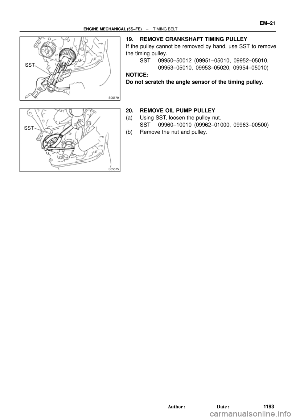
19. REMOVE CRANKSHAFT TIMING PULLEY
If the pulley cannot be removed by hand, use SST to remove
the timing pulley.
SST 09950±50012 (09951±05010, 09952±05010,
09953±05010, 09953±05020, 09954±05010)
NOTICE:
Do not scratch the angle sensor of the timing pulley.
20. REMOVE OIL PUMP PULLEY
(a) Using SST, loosen the pulley nut.
SST 09960±10010 (09962±01000, 09963±00500)
(b) Remove the nut and pulley.

52 (530, 38)6")