Page 2386 of 4770
B06388
No.2 Timing Belt CoverTiming Belt
Gasket
Timing Belt Guide
No.2 Generator
Bracket RH Engine Mounting Bracket
Crankshaft
PulleyGasket
Engine Wire Protector
RH Camshaft Timing PulleyNo.2 Idler Pulley
Dust Boot
Timing Belt Tensioner
� Non±reusable part
*For use with SSTNo.1 Timing Belt Cover
LH Camshaft
Timing Pulley
N´m (kgf´cm, ft´lbf) : Specified torque
28 (290, 21)
215 (2,200, 159)
125 (1,300, 94)*88 (900, 65)
43 (440, 32)
27 (280, 20)
125 (1,300, 94)
CO±4
± COOLING (1MZ±FE)WATER PUMP
1612 Author�: Date�:
Page 2387 of 4770
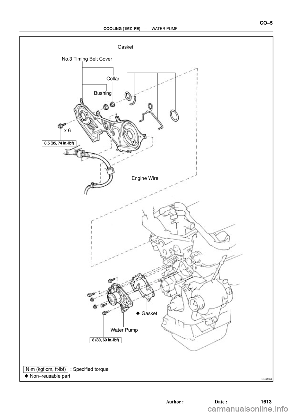
B04403� Non±reusable partNo.3 Timing Belt CoverGasket
Collar
Bushing
Water Pump� Gasket Engine Wire x 6
N´m (kgf´cm, ft´lbf) : Specified torque
8.5 (85, 74 in.´lbf)
8 (80, 69 in.´lbf)
± COOLING (1MZ±FE)WATER PUMP
CO±5
1613 Author�: Date�:
Page 2388 of 4770
CO03E±03
P12942
CO±6
± COOLING (1MZ±FE)WATER PUMP
1614 Author�: Date�:
REMOVAL
1. DRAIN ENGINE COOLANT
2. REMOVE TIMING BELT (See page EM±15)
3. REMOVE CAMSHAFT TIMING PULLEYS
(See page EM±15)
4. REMOVE NO.2 IDLER PULLEY
(See page EM±15)
5. REMOVE NO.3 TIMING BELT COVER
(See page EM±32)
6. REMOVE WATER PUMP
Remove the 4 bolts, 2 nuts, water pump and gasket.
Page 2389 of 4770
CO03F±03
P12487
± COOLING (1MZ±FE)WATER PUMP
CO±7
1615 Author�: Date�:
INSPECTION
1. INSPECT WATER PUMP
(a) Visually check the drain hole for coolant leakage.
If leakage is found, replace the water pump.
(b) Turn the pulley, and check that the water pump bearing
moves smoothly and quietly.
If necessary, replace the water pump.
2. INSPECT TIMING BELT COMPONENTS
(See page EM±19)
Page 2390 of 4770
CO0SO±01
P12942
CO±8
± COOLING (1MZ±FE)WATER PUMP
1616 Author�: Date�:
INSTALLATION
1. INSTALL WATER PUMP
Install a new gasket and the water pump with the 4 bolts and 2
nuts.
Torque: 8 N´m (80 kgf´cm, 69 in.´lbf)
NOTICE:
Do not get oil on the gasket.
2. INSTALL NO.3 TIMING BELT COVER
(See page EM±57)
3. INSTALL NO.2 IDLER PULLEY
(See page EM±21)
4. INSTALL CAMSHAFT TIMING PULLEYS
(See page EM±21)
5. INSTALL TIMING BELT
(See page EM±21)
6. FILL WITH ENGINE COOLANT
7. START ENGINE AND CHECK FOR LEAKS
8. RECHECK ENGINE COOLANT LEVEL
Page 2428 of 4770

243 Author�: Date�:
4. FAIL±SAFE CHART
If any of the following codes is recorded, the ECM enters fail±safe mode.
DTC No.Fail±Safe OperationFail±Safe Deactivatio")
DI±8
± DIAGNOSTICSENGINE (5S±FE)
243 Author�: Date�:
4. FAIL±SAFE CHART
If any of the following codes is recorded, the ECM enters fail±safe mode.
DTC No.Fail±Safe OperationFail±Safe Deactivation Conditions
P0105Ignition timing fixed at 5° BTDCReturned to normal condition
P0110Intake air temperature is fixed at 20°C (68°F)Returned to normal condition
P0115Engine coolant temperature is fixed at 80°(176°F)Returned to normal condition
P0120VTA is fixed at 0°
The following condition must be repeated at least 2 times
consecutively
VTA ��0.1 V and � 0.95 V
P0135
P0141The heater circuit in witch an abnormality is detected is
turned offIgnition switch OFF
P0325Max. timing retardationIgnition switch OFF
P0336Fuel cutReturned to normal condition
P1135The heater circuit in which an abnormality is detected is
turned offIgnition switch OFF
P1300
P1310Fuel cutIGF signal is detected for 2 consecutive ignitions
5. CHECK FOR INTERMITTENT PROBLEMS
TOYOTA HAND±HELD TESTER only:
By putting the vehicle's ECM in check mode, 1 trip detection logic is possible instead of 2 trip detection logic
and sensitivity to detect open circuits is increased. This makes it easier to detect intermittent problems.
(1) Clear the DTC (See page DI±3).
(2) Set the check mode (See page DI±3).
(3) Perform a simulation test (See page IN±21).
(4) Check the connector and terminal (See page IN±31).
(5) Handle the connector (See page IN±31).
6. BASIC INSPECTION
When the malfunction code is not confirmed in the DTC check, troubleshooting should be performed in the
order for all possible circuits to be considered as the causes of the problems. In many cases, by carrying
out the basic engine check shown in the following flow chart, the location causing the problem can be found
quickly and efficiently. Therefore, use of this check is essential in engine troubleshooting.
1 Is battery positive voltage 11 V or more when engine is stopped?
NO Charge or replace battery.
YES
Page 2431 of 4770
A07370S05309A07664
E1 TE1
SST
DLC1
± DIAGNOSTICSENGINE (5S±FE)
DI±11
246 Author�: Date�:
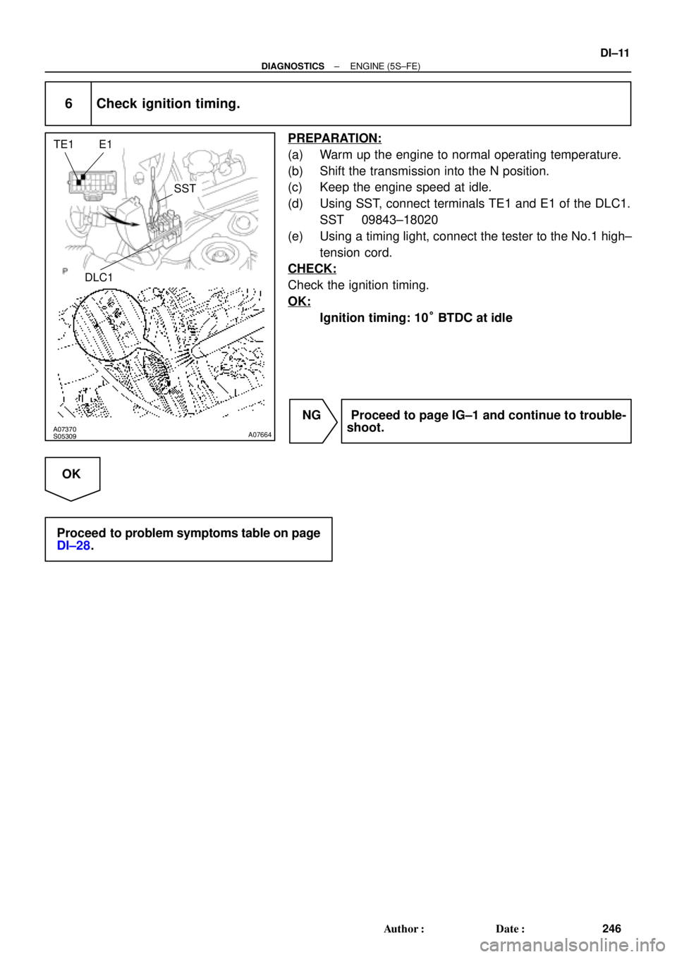
6 Check ignition timing.
PREPARATION:
(a) Warm up the engine to normal operating temperature.
(b) Shift the transmission into the N position.
(c) Keep the engine speed at idle.
(d) Using SST, connect terminals TE1 and E1 of the DLC1.
SST 09843±18020
(e) Using a timing light, connect the tester to the No.1 high±
tension cord.
CHECK:
Check the ignition timing.
OK:
Ignition timing: 10° BTDC at idle
NG Proceed to page IG±1 and continue to trouble-
shoot.
OK
Proceed to problem symptoms table on page
DI±28.
Page 2434 of 4770

249 Author�: Date�:
7. ENGINE OPERATING CONDITION
NOTICE:
The values given below for ºNormal Conditionº are representative values, so a vehicle may still be
norm")
DI±14
± DIAGNOSTICSENGINE (5S±FE)
249 Author�: Date�:
7. ENGINE OPERATING CONDITION
NOTICE:
The values given below for ºNormal Conditionº are representative values, so a vehicle may still be
normal even if its value varies from those listed here. So do not decide whether a part is faulty or
not solely according to the ºNormal Conditionº here.
(a) CARB mandated signals.
TOYOTA hand±held tester displayMeasurement ItemNormal Condition*1
FUEL SYS #1
Fuel System Bank 1
OPEN: Air±fuel ratio feedback stopped
CLOSED: Air±fuel ratio feedback operating
Idling after warming up: CLOSED
CALC LOAD
Calculator Load:
Current intake air volume as a proportion of max.
intake air volumeIdling: 19.7 ~ 50.4 %
Racing without load (2,500rpm): 16.8 ~ 47.4 %
COOLANT TEMP.Engine Coolant Temp. Sensor ValueAfter warming up: 80 ~ 95°C (176 ~ 203°F)
SHORT FT #1Short±term Fuel Trim Bank 10 ± 20 %
LONG FT #1Long±term Fuel Trim Bank 10 ± 20 %
ENGINE SPDEngine SpeedIdling: 650 ~ 750 rpm
VEHICLE SPDVehicle SpeedVehicle Stopped: 0 km/h (0 mph)
IGN ADVANCEIgnition Advance:
Ignition Timing of Cylinder No. 1Idling: BTDC 0 ~ 10°
INTAKE AIRIntake Air Temp. Sensor ValueEquivalent to Ambient Temp.
MAPAbsolute Pressure inside Intake Manifold
Idling: 20 ~ 51 kPa
Racing without load (2,500 rpm):
17 ~ 48 kPa
THROTTLE POS
Voltage Output of Throttle Position Sensor
Calculated as a percentage:
0 V "0%, 5 V "100 %Throttle Fully Closed: 6 ~ 16 %
Throttle Fully Open: 64 ~ 98 %
O2S B1, S1Voltage Output of Heated Oxygen Sensor
Bank 1 Sensor 1Idling: 0.1 ~ 0.9 V (0.56 ~ 0.76 V *2)
O2FT B1, S1
Heated Oxygen Sensor Fuel Trim Bank 1
Sensor 1
(Same as SHORT FT #1)
0 ± 20 %
A/FS B1, S1 *3Voltage Output of A/F SensorIdling: 2.8 ~ 3.8 V
A/FFT B1, S1 *3A/F Sensor Fuel Trim (Same as SHORT FT #1)0 ± 20 %
O2S B1, S2Voltage Output of Heated Oxygen Sensor
Bank 1 Sensor 2Driving at 50 km/h (31 mph): 0.05 ~ 0.95 V
*1: If no conditions are specifically stated for ºldlingº, it means the shift lever is at N or P position, the A/C
switch is OFF and all accessory switches are OFF.
*2: Only for California Specification vehicles, when you use the OBD II scan tool (excluding TOYOTA hand±
held tester).
*3: Only for California Specification vehicles, when you use the TOYOTA hand±held tester.