Page 1221 of 4770

2. CONTROL SYSTEM
*SFI system
The SFI system monitors the engine condition through the signals, which are input from each sensor (Input signals (1) to
(12) ). The best fuel in")
ENGINE CONTROL (1MZ±FE)
2. CONTROL SYSTEM
*SFI system
The SFI system monitors the engine condition through the signals, which are input from each sensor (Input signals (1) to
(12) ). The best fuel injection volume is decided based on this data and the program memorized by the engine control
module, and the control signal is output to TERMINALS #10, #20, #30, #40, #50 and #60 of the engine control module
to operate the injector (Inject the fuel). The SFI system produces control of fuel injection operation by the engine control
module in response to the driving conditions.
*ESA system
The ESA system monitors the engine condition through the signals, which are input to the engine control module from
each sensor (Input signals from 1, 3, 4, 12). The best ignition timing is decided according to this data and the memorized
data in the engine control module and the control signal is output to TERMINALS IGT1, IGT2 and IGT3. This signal
controls the igniter to provide the best ignition timing for the driving conditions.
*Heated oxygen sensor heater control system
The heated oxygen sensor heater control system turns the heater on when the intake air volume is low (Temp. of
exhaust emissions is low), and warms up the heated oxygen sensor to improve detection performance of the sensor.
The engine control module evaluates the signals from each sensor (Input signals from 1, 4, 9, 10), current is output to
TERMINALS HTL, HTR and HTS, controlling the heater.
*Idle air control system
The idle air control system (Rotary solenoid type) increases the RPM and provides idle stability for fast idle±up when the
engine is cold, and when the idle speed has dropped due to electrical load and so on, the engine control module
evaluates the signals from each sensor (Input signals from 1, 4, 5, 8, 9), current is output to TERMINALS RSO and RSC
to control idle air control valve.
*EGR control system
The EGR control system detects the signal from each sensor (Input signals from 1, 4, 9, 10), and outputs current to
TERMINAL EGR to control the VSV (EGR).
The EGR valve position sensor is mounted on the EGR valve. this sensor converts the EGR valve opening height into a
voltage and sends it to the engine control module as the EGR valve position signal.
*ACIS
ACIS includes a valve in the bulkhead separating the surge tank into two parts. This valve is opened and closed in
accordance with the driving conditions to control the intake manifold length in two stages for increased engine output in
all ranges from low to high speeds.
The engine control module judges the engine speed by the signals ( (4), (5) ) from each sensor and outputs signals to
the TERMINAL ACIS to control the VSV (Intake air control).
3. DIAGNOSIS SYSTEM
With the diagnosis system, when there is a malfunction in the engine control module signal system, the malfunctioning
system is recorded in the memory.
4. FAIL±SAFE SYSTEM
When a malfunction occurs in any systems, if there is a possibility of engine trouble being caused by continued control
based on the signals from that system, the fail±safe system either controls the system by using data (Standard values)
recorded in the engine control module memory or else stops the engine.
Page 1236 of 4770
 to (14) etc.) to the engine control module. The")
2. CONTROL SYSTEM
*SFI system
The SFI system monitors the engine condition through the signals, which are input from each sensor (Input signals from
(1) to (14) etc.) to the engine control module. The best fuel injection volume is decided based on this data and the
program memorized by the engine control module, and the control signal is output to TERMINALS #10, #20, #30 and
#40 of the engine control module to operate the injector. (Inject the fuel). The SFI system produces control of fuel
injection operation by the engine control module in response to the driving conditions.
*ESA system
The ESA system monitors the engine condition through the signals, which are input to the engine control module from
each sensor (Input signals from (1), (2), (4) to (12) etc.) the best ignition timing is detected according to this data and the
memorized data in the engine control module, and the control signal is output to TERMINALS IGT1 and IGT2. This
signal controls the igniter to provide the best ignition timing for the driving conditions.
*Idle Air Control system
The IAC system (Step motor type) increases the RPM and provides idling stability for fast idle±up when the engine is
cold and when the idle speed has dropped due to electrical load, etc. The engine control module evaluates the signals
from each sensor (Input signals (1), (4) to (8), (13) etc.), outputs current to TERMINALS ISCO and ISCC, and controls
the idle air control valve.
*Fuel pump control system
The engine control module operation outputs to TERMINAL FC and controls the CIR OPN relay. Thus controls the fuel
pump drive speed in response to conditions.
*EGR control system
The EGR cut control system controls the VSV (EGR) by evaluating the signals from each sensor which are input to the
engine control module (Input signals (1), (5), (6), (9) etc.) and by sending output to TERMINAL EGR of the engine
control module.
*A/C conditioning operation system
In addition to the conventional A/C cut control, the engine control module performs the air conditioning operation as well
since the A/C amplifier function is built in it.
3. DIAGNOSIS SYSTEM
With the diagnosis system, when there is a malfunctioning in the engine control module signal system, the malfunction
system is recorded in the memory. The malfunctioning system can then be found by reading the display (Code) of the
malfunction indicator lamp.
4. FAIL±SAFE SYSTEM
When a malfunction occurs in any system, if there is a possibility of engine trouble being caused by continued control based
on the signals from that system, the fail±safe system either controls the system by using data (Standard values) recorded in
the engine control module memory or else stops the engine.
E7 (A), E8 (B), E9 (C), E10 (D) ENGINE CONTROL MODULE
Voltage at engine control module wiring connector
BATT±E1 : Always 9.0±14.0 volts
+B±E1 :9.0±14.0 volts (Ignition SW at ON position)
VC±E2 :4.5± 5.5 volts (Ignition SW at ON position)
VTA±E2 :0.3± 0.8 volts (Ignition SW on and throttle valve fully closed)
3.2±4.9 volts (Ignition SW on and throttle valve open)
PIM±E2 :3.3± 3.9 volts (Ignition SW at ON position)
THA±E2 :0.5±3.4 volts (Ignition SW on and intake air temp. 20°C, 68°F)
THW±E2 :0.2± 1.0 volts (Ignition SW on and coolant temp. 80°C, 176°F)
STA±E1 :6.0±14.0 volts (Engine cranking)
W±E1 :9.0±14.0 volts (No trouble and engine running)
TE1±E1 :9.0±14.0 volts (Ignition SW at ON position)
NSW±E1 :0± 3.0 volts (Ignition SW on and Park/Neutral position SW position P or N position)
9.0±14.0 volts (Ignition SW on and except Park/Neutral position SW position P or N position)
IGT1, IGT2±E1 : Pulse generation (Engine cranking or idling)
#10, #20, #30, #40±E01, E02 :9.0±14.0 volts (Ignition SW at ON position)
RESISTANCE AT ENGINE CONTROL MODULE WIRING CONNECTORS
(Disconnect wiring connector)
VC±E2 :2.5±5.0 kW
THA±E2 :2.21±2.69 kW (Intake air temp. 20°C, 68°F)
THW±E2 :0.29±0.354 kW (Coolant temp. 80°C, 176°F)
SERVICE HINTS
Page 1640 of 4770
AUTOMATIC TRANSAXLEOPERATION ±
AX±7
2. ELECTRONIC CONTROL SYSTEM
The electronic control system for controlling the shift timing and the operation of the lock±up clutch is
composed of the following 3 parts:
(a) Sensors: These sense the vehicle speed and throttle position and send this data to the ECM in the form
of electronic signals.
(b) ECM: This determines the shift and lock±up timing based upon the signals from the sensors.
(c) Actuators: Solenoid valves divert hydraulic pressure from one circuit of the hydraulic control unit to
another, thus controlling shifting and lock±up timing.
Page 2028 of 4770

BO±69
2417 Author�: Date�:
6. VERIFY CORRECT INSTALLATION TIMING
(a) Cycle the unit once (vent p")
H01821
OK NG
H01822
Guide Pin Lift Arm Assembly
Slide Rail
H01823
Hook
± BODYSLIDING ROOF (TMMK Made)
BO±69
2417 Author�: Date�:
6. VERIFY CORRECT INSTALLATION TIMING
(a) Cycle the unit once (vent position closed, slide open, slide
completely closed).
HINT:
After cycling the unit closed from the slide open position, verify
the alignment holes in the cable arm and cam block are aligned
and the motor pointers are in the ºOº position.
The timing of the sliding roof is okay if the holes are within
1/2 a diameter of each other as shown when closed from
the ºside openº position.
NOTICE:
The holes will normally not align when moving the sliding
roof from the vent open position to the closed position.
(b) There should be a slight interference between the guide
pin and the curved ºlead±inº of the side rail. Confirm by
cycling the unit. A clicking sound from the hook indicates
the adjustment is incorrect.
If the guide pin has been disturbed, readjust as follows:
(1) Loosen the screw and adjust the pin so there is a
slight interference.
(2) Tighten the screw and cycle the unit.
(3) Confirm the hook smoothly engages the wind de-
flector spring.
(4) Repeat if necessary.
7. REINSTALL GLASS PANEL
Page 2352 of 4770
S05939
No.2 Timing Belt
Cover
No.1 Timing Belt
Cover
Crankshaft
Pulley
No.2 Idler Pulley
Generator Drive Belt
Adjusting Bar
Wire Clamp
Crankshaft Position Sensor
Connector* Gasket
No.1 Idler Pulley
Tension Spring
� O±Ring
Water PumpWater PumpTiming Belt
Timing Belt Guide
Lower
Radiator
Hose Water Pump and
Water Pump Cover
Assembly High±Tension Cord Generator Wire
� Gasket Wire Clamp
Wire Clamp
Wire ClampWire Clamp Wire
Clamp
* GasketGenerator Connector
Generator
Spark Plug
� O±Ring
� Gasket
N´m (kgf´cm, ft´lbf): Specified torque
� Non±reusable part
108 (1,100, 80)18 (180,13)
42 (425,31)
42 (425,31)
* Replace only if damagedCover CO±4
± COOLING (5S±FE)WATER PUMP
1578 Author�: Date�:
Page 2353 of 4770
CO069±04
S05599
S05924
S05963
1
2
3
± COOLING (5S±FE)WATER PUMP
CO±5
1579 Author�: Date�:
REMOVAL
1. DRAIN ENGINE COOLANT
2. REMOVE TIMING BELT (See page EM±17)
3. DISCONNECT LOWER RADIATOR HOSE FROM WA-
TER OUTLET
4. REMOVE TIMING BELT TENSION SPRING
Loosen the No.1 idler pulley bolt, and remove the tension
spring.
5. REMOVE NO.2 IDLER PULLEY
Remove the bolt and idler pulley.
6. w/ Oil Cooler:
REMOVE A/C COMPRESSOR (See page EM±69)
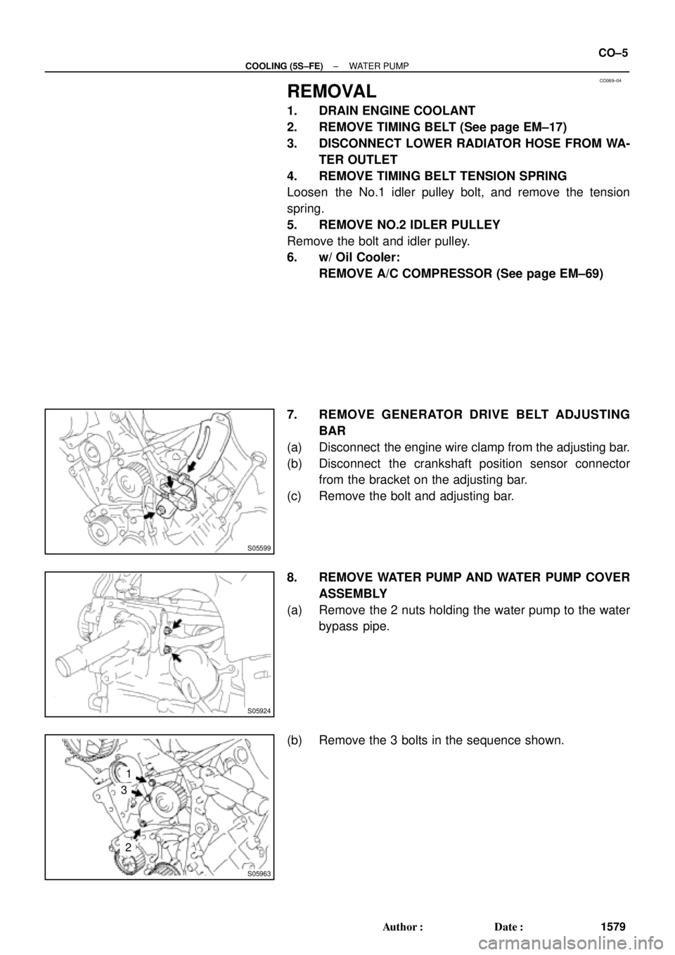
7. REMOVE GENERATOR DRIVE BELT ADJUSTING
BAR
(a) Disconnect the engine wire clamp from the adjusting bar.
(b) Disconnect the crankshaft position sensor connector
from the bracket on the adjusting bar.
(c) Remove the bolt and adjusting bar.
8. REMOVE WATER PUMP AND WATER PUMP COVER
ASSEMBLY
(a) Remove the 2 nuts holding the water pump to the water
bypass pipe.
(b) Remove the 3 bolts in the sequence shown.
Page 2355 of 4770
CO06A±03
S01486
Turn
Air Hole
± COOLING (5S±FE)WATER PUMP
CO±7
1581 Author�: Date�:
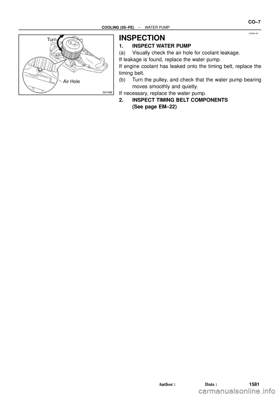
INSPECTION
1. INSPECT WATER PUMP
(a) Visually check the air hole for coolant leakage.
If leakage is found, replace the water pump.
If engine coolant has leaked onto the timing belt, replace the
timing belt.
(b) Turn the pulley, and check that the water pump bearing
moves smoothly and quietly.
If necessary, replace the water pump.
2. INSPECT TIMING BELT COMPONENTS
(See page EM±22)
Page 2357 of 4770
± COOLING (5S±FE)WATER PUMP
CO±9
1583 Author�: Date�:
6. INSTALL TIMING BELT TENSION SPRING
(See page EM±23)
7. CONNECT LOWER RADIATOR HOSE TO WATER IN-
LET
8. INSTALL TIMING BELT (See page EM±23)
9. FILL WITH ENGINE COOLANT
10. START ENGINE AND CHECK FOR COOLANT LEAKS