Page 358 of 4770

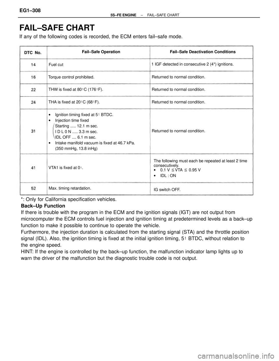
*: Only for California specification vehicles.
Back±Up Function
If there is trouble with the program in the ECM and the ignition signals (IGT) are not output from
microcomputer the ECM controls fuel injection and ignition timing at predetermined levels as a back±up
function to make it possible to continue to operate the vehicle.
Furthermore, the injection duration is calculated from the starting signal (STA) and the throttle position
signal (IDL). Also, the ignition timing is fixed at the initial ignition timing, 5� BTDC, without relation to
the engine speed.
HINT: If the engine is controlled by the back±up function, the malfunction indicator lamp lights up to
warn the driver of the malfunction but the diagnostic trouble code is not output.
FAIL±SAFE CHART
If any of the following codes is recorded, the ECM enters fail±safe mode.
wIgnition timing fixed at 5� BTDC.
wInjection time fixed
Starting ..... 12.1 m sec.
I D L 0 N ..... 3.3 m sec.
IDL OFF .... 6.1 m sec.
wIntake manifold vacuum is fixed at 46.7 kPa.
(350 mmHg, 13.8 inHg)
The following must each be repeated at least 2 time
consecutively.
w0.1 V �VTA � 0.95 V
wIDL : ON 1 IGF detected in consecutive 2 (4*) ignitions.Fail±Safe Deactivation Conditions
THW is fixed at 80�C (176�F).
THA is fixed at 20�C (68�F). Returned to normal condition.Returned to normal condition.
Returned to normal condition. Returned to normal condition. Torque control prohibited.
Max. timing retardation.Fail±Safe Operation
VTA1 is fixed at 0
�.
IG switch OFF. DTC No.
Fuel cut
± 5S±FE ENGINEFAIL±SAFE CHARTEG1±308
Page 361 of 4770

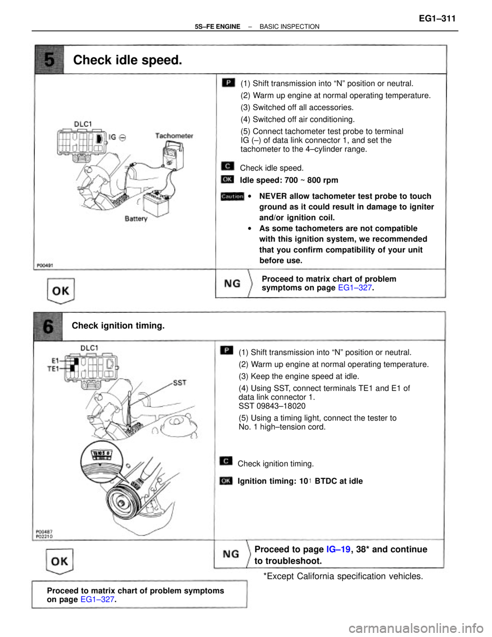
(1) Shift transmission into ªNº position or neutral.
(2) Warm up engine at normal operating temperature.
(3) Keep the engine speed at idle.
(4) Using SST, connect terminals TE1 and E1 of
data link connector 1.
SST 09843±18020
(5) Using a timing light, connect the tester to
No. 1 high±tension cord.(1) Shift transmission into ªNº position or neutral.
(2) Warm up engine at normal operating temperature.
(3) Switched off all accessories.
(4) Switched off air conditioning.
(5) Connect tachometer test probe to terminal
IG (±) of data link connector 1, and set the
tachometer to the 4±cylinder range.
wNEVER allow tachometer test probe to touch
ground as it could result in damage to igniter
and/or ignition coil.
wAs some tachometers are not compatible
with this ignition system, we recommended
that you confirm compatibility of your unit
before use.
Proceed to matrix chart of problem symptoms
on page EG1±327.
Proceed to page IG±19, 38* and continue
to troubleshoot.
Proceed to matrix chart of problem
symptoms on page EG1±327.
*Except California specification vehicles. Check ignition timing.
Check idle speed.
Check idle speed.
Idle speed: 700 ~ 800 rpm
Check ignition timing.
Ignition timing: 10� BTDC at idle
± 5S±FE ENGINEBASIC INSPECTIONEG1±311
Page 394 of 4770

CIRCUIT DESCRIPTION
The ECM determines the ignition timing, turns on Tr, at a predetermined angle ('*CA) before the
desired ignition timing and outputs an ignition signal (IGT) ª1º to the igniter.
Since the width of the IGT signal is constant, the dwell angle control circuit in the igniter determines
the time the control circuit starts primary current flow to the ignition coil based on the engine rpm and
ignition timing one revolution ago, that is, the time the Tr
2 turns on.
When it reaches the ignition timing, the ECM turns Tr, off and outputs the IGT signal ªOº.
This turns Tr2 off, interrupting the primary current flow and generating a high voltage in the secondary
coil which causes the spark plug to spark. Also, by the counter electromotive force generated when
the primary current is interrupted, the igniter sends an ignition confirmation signal (IGF) to the ECM.
The ECM stops fuel injection as a fail safe function when the lG F signal is not input to the ECM.
wOpen or short in IG F or IGT circuit from
igniter to ECM.
wIgniter
wECM No IGF signal to ECM for 4 (8*2) consecutive
IGT signals. Diagnostic Trouble Code Detecting Condition
WIRING DIAGRAM
Trouble Area
DTC 14 Ignition Signal Circuit
DTC No.
± 5S±FE ENGINECIRCUIT INSPECTIONEG1±344
Page 401 of 4770
CIRCUIT DESCRIPTION
The signal from the A/T CPU retards the ignition timing of the engine during A/T shifting, thus
momentarily reducing torque output of the engine for smooth clutch operation inside the transmis-
sion and reduced shift shock.
If the ECM detects the diagnostic trouble code ª16º in memory, it prohibits the torque control of the
A/T which performs smooth gear shifting.
Are there any other codes (besides Code 16)
being output?Fault in communications between the engine
CPU and A/T CPU in the ECM
Go to relevant diagnostic trouble code
chart. Diagnostic Trouble Code Detecting Condition
DIAGNOSTIC CHART
Replace ECM.Trouble Area
DTC 16 A±T Control Signal Malfunction
DTC No.
wECM
YES
± 5S±FE ENGINECIRCUIT INSPECTIONEG1±351
Page 413 of 4770

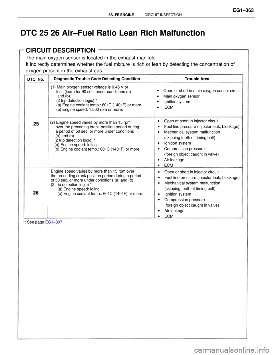
CIRCUIT DESCRIPTION
The main oxygen sensor is located in the exhaust manifold.
It indirectly determines whether the fuel mixture is rich or lean by detecting the concentration of
oxygen present in the exhaust gas.
Engine speed varies by more than 15 rpm over
the preceding crank position period during a period
of 50 sec. or more under conditions (a) and (b).
(2 trip detection logic) *
(a) Engine speed: Idling
(b) Engine coolant temp.: 60�C (140�F) or more (2) Engine speed varies by more than 15 rpm
over the preceding crank position period during
a period of 50 sec. or more under conditions
(a) and (b).
(2 trip detection logic) *
(a) Engine speed: Idling
(b) Engine coolant temp.: 60�C (140�F) or more.wOpen or short in injector circuit
wFuel line pressure (injector leak, blockage)
wMechanical system malfunction
(skipping teeth of timing belt)
wIgnition system
wCompression pressure
(foreign object caught in valve)
wAir leakage
wECM
wOpen or short in injector circuit
wFuel line pressure (injector leak, blockage)
wMechanical system malfunction
(skipping teeth of timing belt)
wIgnition system
wCompression pressure
(foreign object caught in valve)
wAir leakage
wECM (1) Main oxygen sensor voltage is 0.45 V or
less (lean) for 90 sec. under conditions (a)
and (b).
(2 trip detection logic) *
(a) Engine coolant temp.: 60�C (140�F) or more.
(b) Engine speed: 1,500 rpm or more.wOpen or short in main oxygen sensor circuit
wMain oxygen sensor
wIgnition system
w ECM Diagnostic Trouble Code Detecting Condition
*: See page EG1±307Trouble Area
DTC 25 26 Air±Fuel Ratio Lean Rich Malfunction
DTC No.
± 5S±FE ENGINECIRCUIT INSPECTIONEG1±363
Page 417 of 4770

Check each circuit found to be a possible cause of trouble according to the results of the check in
or . The numbers in the table below show the order in which the checks should be performed.Check for open and short in harness and connector between engine control module and
main oxygen sensor, engine control module and data link connector 1 (See page
IN±31).
Does malfunction disappear when a good main oxygen sensor is
installed?Check each item found to be a possible cause of problem.
Check compression (See page EG1±23).
Repair or replace harness or connector.
Check and replace engine control module.
Characteristics deviation in
manifold absolute pressure sensor.
Characteristics deviation
in engine coolant temp. sensor.
Replace main oxygen sensor.
*: Except California specification vehicles.Characteristics deviation
in intake air temp. sensor. Main oxygen sensor
signal continue at OV.
Repair or replace.
Repair or replace.
Faulty sensor installation.Possible Cause
Injector circuit
Valve timing
Fuel system Air leakageSee page
IG±6, 26*
YES
EG1±410
EG1±360 EG1±419
EG1±372 EG1±173
EG1±356 Misfire
EG1±36
± 5S±FE ENGINECIRCUIT INSPECTIONEG1±367
Page 418 of 4770
Check each circuit found to be a possible cause of trouble according to the results of the check in
.The numbers in the table below show the order in which the checks should be performed.
Does malfunction disappear when a good main oxygen sensor is
installed? Check each item found to be a possible cause of problem.
Check compression (See page EG1±23).
Check and replace engine control module.
Characteristics deviation
in engine coolant temp. sensor.
Characteristics deviation in
manifold absolute pressure sensor.
Replace main oxygen sensor.
Main oxygen sensor
signal continue at 5.0 V.
x: Except California specification vehicles.Characteristics deviation
in intake air temp. sensor. Main oxygen sensor
signal is normal.
Repair or replace.
Repair or replace.
Possible Cause
Injector circuit
Valve timing
Fuel system Air leakageSee page
IG±6, 26*
YES
EG1±410
EG1±360 EG1±419
EG1±372 EG1±173
EG1±356 Misfire
EG1±36
± 5S±FE ENGINECIRCUIT INSPECTIONEG1±368
Page 422 of 4770

CIRCUIT DESCRIPTION
By a built±in sensor unit, the manifold absolute
pressure sensor detects the intake manifold absolute
pressure as a voltage.
The ECM then determines the basic injection dura±
tion and basic ignition advance angle based on this
voltage.
Since the manifold absolute pressure sensor does
not use the atmospheric pressure as a criterion, but
senses the absolute pressure inside the intake man±
ifold (the pressure in proportion to the preset abso±
lute vacuum O), it is not influenced by fluctuations
in the atmospheric, pressure due to high altitude
and other factors. This permits it to control the air±
fuel ratio at the proper level under all conditions.
If the ECM detect diagnostic trouble code ª31 ª, it operates the fail safe function, keeping the ignition
timing and fuel injection volume constant and making it possible to drive the vehicle.w
Open or short in manifold absolute pressure
sensor circuit.
wManifold absolute pressure sensor.
wECM Open or short in manifold absolute pressure sensor
circuit for 0.5 sec. or more.Diagnostic Trouble Code Detecting Condition Trouble Area
DTC 31 Manifold Absolute Pressure Sensor Circuit
DTC No.
± 5S±FE ENGINECIRCUIT INSPECTIONEG1±372