Page 3507 of 4770

EM04I±04
S04994
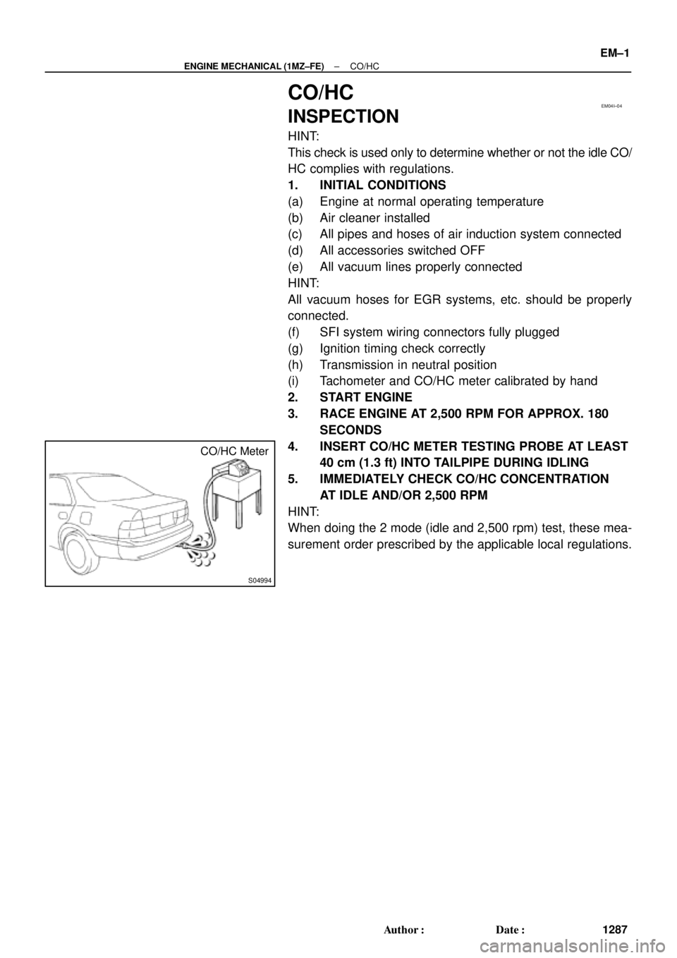
CO/HC Meter
± ENGINE MECHANICAL (1MZ±FE)CO/HC
EM±1
1287 Author�: Date�:
CO/HC
INSPECTION
HINT:
This check is used only to determine whether or not the idle CO/
HC complies with regulations.
1. INITIAL CONDITIONS
(a) Engine at normal operating temperature
(b) Air cleaner installed
(c) All pipes and hoses of air induction system connected
(d) All accessories switched OFF
(e) All vacuum lines properly connected
HINT:
All vacuum hoses for EGR systems, etc. should be properly
connected.
(f) SFI system wiring connectors fully plugged
(g) Ignition timing check correctly
(h) Transmission in neutral position
(i) Tachometer and CO/HC meter calibrated by hand
2. START ENGINE
3. RACE ENGINE AT 2,500 RPM FOR APPROX. 180
SECONDS
4. INSERT CO/HC METER TESTING PROBE AT LEAST
40 cm (1.3 ft) INTO TAILPIPE DURING IDLING
5. IMMEDIATELY CHECK CO/HC CONCENTRATION
AT IDLE AND/OR 2,500 RPM
HINT:
When doing the 2 mode (idle and 2,500 rpm) test, these mea-
surement order prescribed by the applicable local regulations.
Page 3508 of 4770

EM±2
± ENGINE MECHANICAL (1MZ±FE)CO/HC
1288 Author�: Date�:
If the CO/HC concentration dose not comply with regulations,
troubleshoot in the order given below.
See the table below for possible causes, then inspect and cor-
rect the applicable causes if necessary.
COHCProblemsCauses
NormalHighRough idle1. Faulty ignitions:
�Incorrect timin
g�Incorrect timing
�Fouled, shorted or improperly gapped plugs
�Open or crossed hi
gh±tension cords�Oen or crossed high±tension cords
2. Incorrect valve clearance
3 Leaky EGR valve
3 Leaky EGR valve
4.Leaky intake and exhaust valves
5.Leaky cylinder
LowHighRough idle1. Vacuum leaks:LowHighRough idle
(
Filtrating HC reading)
1. Vacuum leaks:
�PCV hose(Filtrating HC reading)�PCV hose
�EGR valve�EGR valve
�Intake manifold�Intake manifold
�Air intake chamber�Air intake chamber
�Throttle bodyThrottle body
�IAC valveIAC valve
�Brake booster lineBrake booster line
2. Lean mixture causing misfire
HighHighRough idle
(Black smoke from exhaust)1. Restricted air filter
2. Faulty SFI system
�Faulty pressure regulator
�Defective ECT sensor
�Faulty ECM
�Faulty injectors
�Faulty throttle position sensor
�Faulty MAF meter
Page 3510 of 4770

EM04K±04
P18805
P13074
RH EX
RH IN
LH IN
LH EX 13
6
23
1
6
2Front EM±4
± ENGINE MECHANICAL (1MZ±FE)VALVE CLEARANCE
1290 Author�: Date�:
VALVE CLEARANCE
INSPECTION
HINT:
Inspect and adjust the valve clearance when the engine is cold.
1. REMOVE RH FENDER APRON SEAL
2. DRAIN ENGINE COOLANT
3. REMOVE V±BANK COVER
(a) Using a 5 mm hexagon wrench, remove the 2 nuts.
(b) Disconnect the 2 clips, and remove the cover.
4. REMOVE HIGH±TENSION CODE SET
(See page IG±7)
5. REMOVE AIR INTAKE CHAMBER ASSEMBLY
(See page EM±32)
6. REMOVE IGNITION COILS
7. DISCONNECT RADIATOR HOSE FROM WATER
OUTLET
8. REMOVE CYLINDER HEAD COVERS
(See page EM±32)
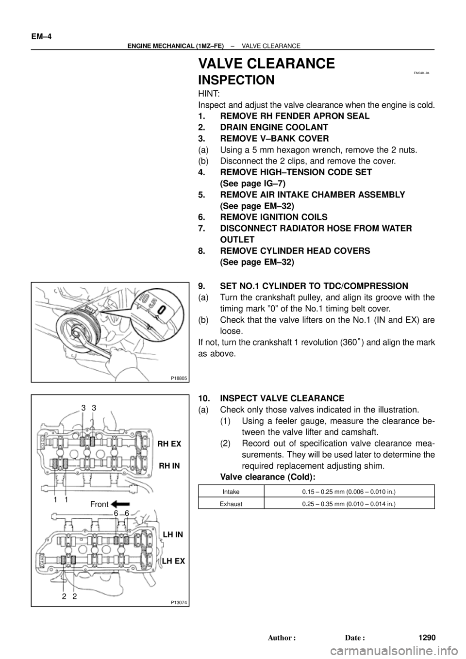
9. SET NO.1 CYLINDER TO TDC/COMPRESSION
(a) Turn the crankshaft pulley, and align its groove with the
timing mark º0º of the No.1 timing belt cover.
(b) Check that the valve lifters on the No.1 (IN and EX) are
loose.
If not, turn the crankshaft 1 revolution (360°) and align the mark
as above.
10. INSPECT VALVE CLEARANCE
(a) Check only those valves indicated in the illustration.
(1) Using a feeler gauge, measure the clearance be-
tween the valve lifter and camshaft.
(2) Record out of specification valve clearance mea-
surements. They will be used later to determine the
required replacement adjusting shim.
Valve clearance (Cold):
Intake0.15 ± 0.25 mm (0.006 ± 0.010 in.)
Exhaust0.25 ± 0.35 mm (0.010 ± 0.014 in.)
Page 3516 of 4770

EM04L±03
S05358
Hand±Held Tester TOYOTA
S04529
E1DLC1
SST
TE1
DLC1
A06644
EM±10
± ENGINE MECHANICAL (1MZ±FE)IGNITION TIMING
1296 Author�: Date�:
IGNITION TIMING
INSPECTION
1. WARM UP ENGINE
Allow the engine to warm up to normal operating temperature.
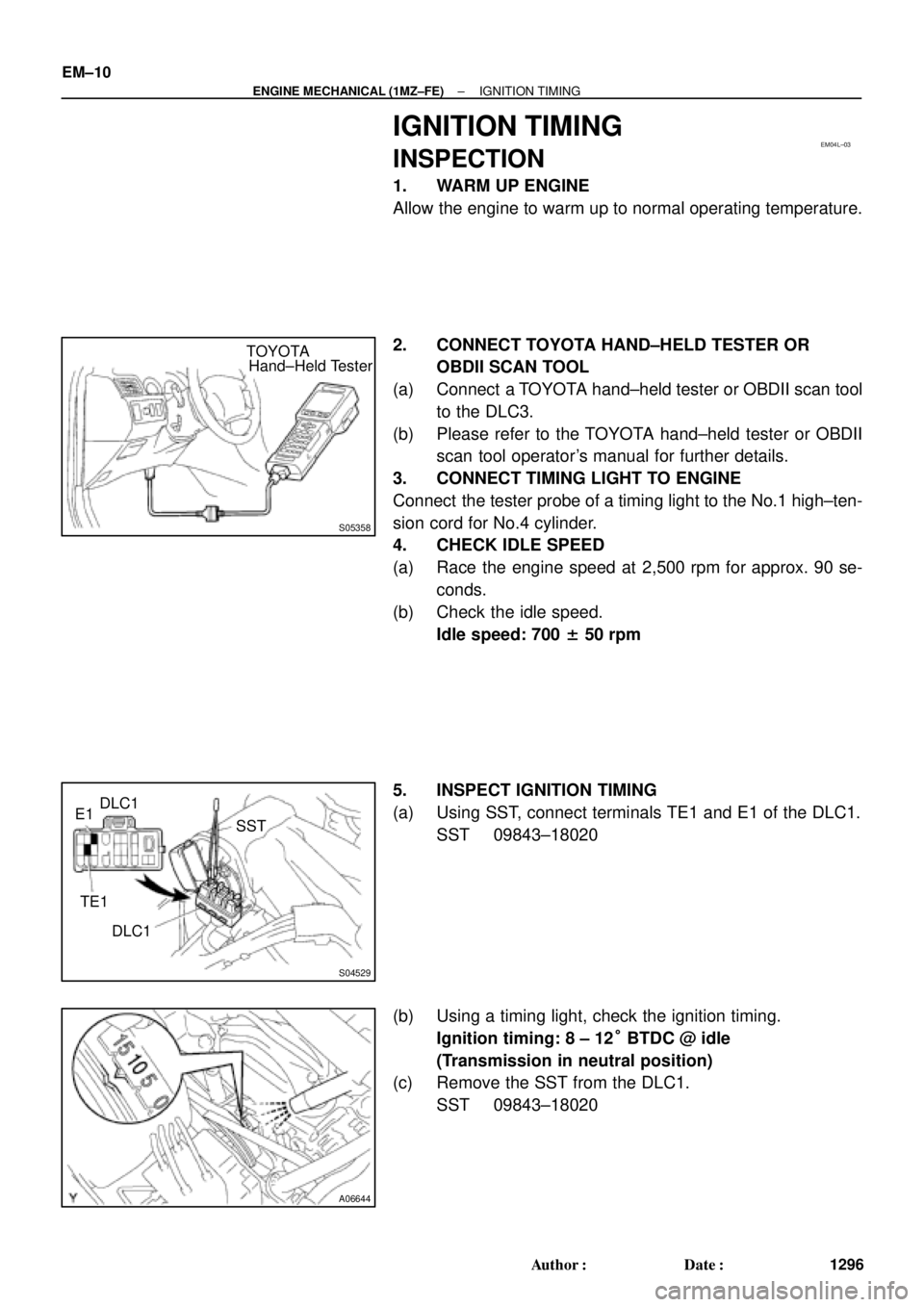
2. CONNECT TOYOTA HAND±HELD TESTER OR
OBDII SCAN TOOL
(a) Connect a TOYOTA hand±held tester or OBDII scan tool
to the DLC3.
(b) Please refer to the TOYOTA hand±held tester or OBDII
scan tool operator's manual for further details.
3. CONNECT TIMING LIGHT TO ENGINE
Connect the tester probe of a timing light to the No.1 high±ten-
sion cord for No.4 cylinder.
4. CHECK IDLE SPEED
(a) Race the engine speed at 2,500 rpm for approx. 90 se-
conds.
(b) Check the idle speed.
Idle speed: 700 ± 50 rpm
5. INSPECT IGNITION TIMING
(a) Using SST, connect terminals TE1 and E1 of the DLC1.
SST 09843±18020
(b) Using a timing light, check the ignition timing.
Ignition timing: 8 ± 12° BTDC @ idle
(Transmission in neutral position)
(c) Remove the SST from the DLC1.
SST 09843±18020
Page 3517 of 4770
± ENGINE MECHANICAL (1MZ±FE)IGNITION TIMING
EM±11
1297 Author�: Date�:
6. FURTHER CHECK IGNITION TIMING
Ignition timing: 7 ± 24° BTDC @ idle
(Transmission in neutral position)
HINT:
The timing mark moves in a range between 7° and 24°.
7. DISCONNECT TIMING LIGHT FROM ENGINE
8. DISCONNECT TOYOTA HAND±HELD TESTER OR
OBDII SCAN TOOL
Page 3518 of 4770
EM0YN±01
EM±12
± ENGINE MECHANICAL (1MZ±FE)IDLE SPEED
1298 Author�: Date�:
IDLE SPEED
INSPECTION
1. INITIAL CONDITIONS
(a) Engine at normal operating temperature
(b) Air cleaner installed
(c) All pipes and hoses of air induction system connected
(d) All accessories switched OFF
(e) All vacuum lines properly connected
HINT:
All vacuum hoses for EGR system, etc. should be properly connected.
(f) SFI system wiring connectors fully plugged
(g) Ignition timing check correctly
(h) Transmission in neutral position
2. CONNECT TOYOTA HAND±HELD TESTER OR OBDII SCAN TOOL (See page EM±10)
3. INSPECT IDLE SPEED
(a) Race the engine speed at 2,500 rpm for approx. 90 seconds.
(b) Check the idle speed.
Idle speed: 700 ± 50 rpm
If the idle speed is not as specified, check the IAC valve and air intake system.
4. DISCONNECT TOYOTA HAND±HELD TESTER OR OBDII SCAN TOOL
Page 3519 of 4770
EM04N±03
A06654
RH Fender Apron Seal
Generator Drive Belt Engine Moving
Control Rod
RH Engine Mounting Stay
No.2 RH Engine
Mounting Bracket
Ground Strap PS Pump Drive Belt
Engine Coolant Reservoir Hose
: Specified torqueNo.2 RH Engine
Mounting Stay (M/T)
64 (650, 47)
32 (320, 23)
64 (650, 47)
N´m (kgf´cm, ft´lbf)
± ENGINE MECHANICAL (1MZ±FE)TIMING BELT
EM±13
1299 Author�: Date�:
TIMING BELT
COMPONENTS
Page 3520 of 4770
B06384
No.2 Timing Belt CoverTiming Belt
Gasket
Timing Belt Guide
No.2 Generator
Bracket RH Engine Mounting Bracket
Crankshaft
PulleyGasket
Engine Wire
Protector
RH Camshaft Timing Pulley
No.2 Idler Pulley
Crankshaft
Timing PulleyDust Boot
Timing Belt Plate Plate Washer
�
Timing Belt Tensioner
N´m (kgf´cm, ft´lbf)
: Specified torque
� Non±reusable part No.1 Timing Belt Cover
LH Camshaft
Timing Pulley
No.1 Idler Pulley
� Precoated part
* For use with SST
28 (290, 21)
215 (2,200, 159)
125 (1,300, 94)*88 (900, 65)43 (440, 32)
34 (350, 25)
27 (280, 20)
125 (1,300, 94)
EM±14
± ENGINE MECHANICAL (1MZ±FE)TIMING BELT
1300 Author�: Date�: