Page 3544 of 4770
CYLINDER HEAD
1324 Author�: Date�:
HINT:
When removing the camshaft, mark ce")
P12780
Intake
7 85 6
3 41 2
9 10
P12888
7
85
6
3
41
2
9
10 Exhaust
P12917
Align Intake EM±38
± ENGINE MECHANICAL (1MZ±FE)CYLINDER HEAD
1324 Author�: Date�:
HINT:
When removing the camshaft, mark certain that the torsional
spring force of the sub±gear has been eliminated by the above
operation.
(3) Uniformly loosen and remove the 10 bearing cap
bolts, in several passes, in the sequence shown.
(4) Remove the 5 bearing caps and intake camshaft.
(b) Remove the exhaust camshaft.
(1) Uniformly loosen and remove the 10 bearing cap
bolts, in several passes, in the sequence shown.
(2) Remove the 5 bearing caps, oil seal and exhaust
camshaft.
32. REMOVE CAMSHAFTS OF LH CYLINDER HEAD
NOTICE:
Since the thrust clearance of the camshaft is small, the
camshaft must be held level while it is being removed. If the
camshaft is not kept level, the portion of the cylinder head
receiving the shaft thrust may crack or be damaged, caus-
ing the camshaft to seize or break. To avoid this, the follow-
ing steps should be carried out.
(a) Remove the intake camshaft.
(1) Align the timing marks (1 dot mark) of the camshaft
drive and driven gears by turning the camshaft with
a wrench.
Page 3565 of 4770
CYLINDER HEAD
EM±59
1345 Author�: Date�:
(e) Using SST, align the hole")
P12974
SST
Main Gear
Sub±Gear
P12963
90°Exhaust
P12804
Exhaust
Front
A02008
Exhaust
Seal
Packing
± ENGINE MECHANICAL (1MZ±FE)CYLINDER HEAD
EM±59
1345 Author�: Date�:
(e) Using SST, align the holes of the camshaft main gear and
sub±gear by turning camshaft sub±gear counterclock-
wise, and temporarily install a service bolt.
SST 09960±10010 (09962±01000, 09963±00500)
(f) Align the gear teeth of the main gear and sub±gear, and
tighten the service bolt.
5. INSTALL CAMSHAFTS OF RH CYLINDER HEAD
NOTICE:
Since the thrust clearance of the camshaft is small, the
camshaft must be held level while it is being installed. If the
camshaft is not level, the portion of the cylinder head re-
ceiving the shaft thrust may crack or be damaged, causing
the camshaft to seize or break. To avoid this, the following
steps should be carried out.
(a) Install the exhaust camshaft.
(1) Apply new engine oil to the thrust portion and jour-
nal of the camshaft.
(2) Place the exhaust camshaft at 90° angle of timing
mark (2 dot marks) on the cylinder head.
(3) Apply MP grease to a new oil seal lip.
(4) Install the oil seal to the camshaft.
(5) Remove any old packing (FIPG) material.
(6) Apply seal packing to the No.1 bearing cap as
shown.
Seal packing: Part No. 08826±00080 or equivalent
Page 3566 of 4770
CYLINDER HEAD
1346 Author�: Date�:
(b) Install th")
P12890
Exhaust
P12887
Exhaust
8
76
5
4
32
19 10
P12875
Intake
Align
P12798
Intake
P25422
Intake
8 76 5
4 32 19
10
EM±60
± ENGINE MECHANICAL (1MZ±FE)CYLINDER HEAD
1346 Author�: Date�:
(b) Install the 5 bearing caps in their proper locations.
(c) Apply a light coat of engine oil on the threads and under
the heads of the bearing cap bolts.
(d) Install and uniformly tighten the 10 bearing cap bolts, in
several passes, in the sequence shown.
Torque: 16 N´m (160 kgf´cm, 12 ft´lbf)
(e) Install the Intake camshaft.
(1) Apply new engine oil to the thrust portion and jour-
nal of the camshaft.
(2) Align the timing marks (2 dot marks) of the camshaft
drive and driven gears.
(3) Place the intake camshaft on the cylinder head.
(4) Install the 5 bearing caps in their proper locations.
(5) Apply a light coat of engine oil on the threads and
under the heads of the bearing cap bolts.
(6) Install and uniformly tighten the 10 bearing cap
bolts, in several passes, in the sequence shown.
Torque: 16 N´m (160 kgf´cm, 12 ft´lbf)
Page 3567 of 4770
CYLINDER HEAD
EM±61
1347 Author�: Date�:
(7) Remove the service bolt.
6. I")
P12870Service Bolt
Intake
P12884
Exhaust
90°
P12805
Exhaust
Front
A02008
Exhaust
Seal
Packing
± ENGINE MECHANICAL (1MZ±FE)CYLINDER HEAD
EM±61
1347 Author�: Date�:
(7) Remove the service bolt.
6. INSTALL CAMSHAFTS OF LH CYLINDER HEAD
NOTICE:
Since the thrust clearance of the camshaft is small, the
camshaft must be held level while it is being installed. If the
camshaft is not level, the portion of the cylinder head re-
ceiving the shaft thrust may crack or be damaged, causing
the camshaft to seize or break. To avoid this, the following
steps should be carried out.
(a) Install the exhaust camshaft.
(1) Apply new engine oil to the thrust portion and jour-
nal of the camshaft.
(2) Place the exhaust camshaft at 90° angle of timing
mark (1 dot mark) on the cylinder head.
(3) Apply MP grease to a new oil seal lip.
(4) Install the oil seal to the camshaft.
(5) Remove any old packing (FIPG) material.
(6) Apply seal packing to the No.1 bearing cap as
shown.
Seal packing: Part No. 08826±00080 or equivalent
Page 3568 of 4770
CYLINDER HEAD
1348 Author�: Date�:
(7) Install t")
P12962
Exhaust
P25421
Exhaust
86 5
4 32 19
10
7
P12874
Intake
Align
P12961
Intake
P12959
Intake
6
5
4
32
19 10
7 8 EM±62
± ENGINE MECHANICAL (1MZ±FE)CYLINDER HEAD
1348 Author�: Date�:
(7) Install the 5 bearing caps in their proper locations.
(8) Apply a light coat of engine oil on the threads and
under the heads of the bearing cap bolts.
(9) Install and uniformly tighten the 10 bearing cap
bolts, in several passes, in the sequence shown.
Torque: 16 N´m (160 kgf´cm, 12 ft´lbf)
(b) Install the intake camshaft.
(1) Apply new engine oil to the thrust portion and jour-
nal of the camshaft.
(2) Align the timing marks (1 dot mark) of the camshaft
drive and driven gears.
(3) Place the intake camshaft on the cylinder head.
(4) Install the 5 bearing caps in their proper locations.
(5) Apply a light coat of engine oil on the threads and
under the heads of bearing cap bolts.
(6) Install and uniformly tighten the 10 bearing cap
bolts, in several passes, in the sequence shown.
Torque: 16 N´m (160 kgf´cm, 12 ft´lbf)
Page 3571 of 4770
Except California A/T
S04789
Ground
Strap
Inlet PipeRear
Plate
± ENGINE MECHANICAL (1MZ±FE)CYLINDER HEAD
EM±65
1351")
P12710
New O±Ring
A01522
Manifold
Stay California A/T
Manifold Stay
(Except M/T)Except California A/T
S04789
Ground
Strap
Inlet PipeRear
Plate
± ENGINE MECHANICAL (1MZ±FE)CYLINDER HEAD
EM±65
1351 Author�: Date�:
13. INSTALL OIL DIPSTICK AND GUIDE
(a) Install a new O±ring to the dipstick guide.
(b) Apply soapy water to the O±ring.
(c) Push in the dipstick guide end into the guide hole of the
No.1 oil pan.
(d) Install the dipstick guide with the bolt.
Torque: 8 N´m (80 kgf´cm, 69 in.´lbf)
(e) Install the dipstick.
14. INSTALL CAMSHAFT POSITION SENSOR
15. INSTALL LH EXHAUST MANIFOLD
(a) Install a new gasket and the exhaust manifold with the 6
nuts. Uniformly tighten the nuts in several passes.
Torque: 49 N´m (500 kgf´cm, 36 ft´lbf)
(b) Except M/T:
Install the exhaust manifold stay with the bolt and nut. Al-
ternately tighten the bolt and nut.
Torque:
California A/T:
34 N´m (350 kgf´cm, 25 ft´lbf)
Except California A/T:
20 N´m (200 kgf´cm, 15 ft´lbf)
(c) California:
Connect the A/F sensor connector.
(d) Except California:
Connect the heated oxygen sensor (bank 2 sensor 1)
connector.
16. INSTALL WATER INLET PIPE
(a) Install a new O±ring to the water inlet pipe.
(b) Apply soapy water to the O±ring.
(c) Connect the water inlet pipe to the water inlet.
(d) Install the bolt holding the water inlet pipe to the cylinder
head.
Torque: 19.5 N´m (200 kgf´cm, 14 ft´lbf)
17. INSTALL CYLINDER HEAD REAR PLATE
Torque: 8 N´m (80 kgf´cm, 69 in.´lbf)
18. INSTALL ENGINE WIRE PROTECTOR
19. INSTALL NO.3 TIMING BELT COVER
(a) Check that the timing belt cover gaskets have no cracks
or peeling, etc.
If the gaskets have cracks or peeling etc., replace them using
these steps:
�Using a screwdriver and gasket scraper, remove all
the old gasket material.
�Thoroughly clean all components to remove all the
loose material.
Page 3572 of 4770

L = 180 mm (7.09 in.)L = 72 mm (2.83 in.)
L = 335 mm (13.19 in.)L = 180 mm
(7.09 in.)
L = Length Join
LineJoin
Line
Z14262New Gasket
A01808
8
6
5
4
3
2
1
9
10
7
11
EM")
A05194
L = 133 mm (5.24 in.)
L = 180 mm (7.09 in.)L = 72 mm (2.83 in.)
L = 335 mm (13.19 in.)L = 180 mm
(7.09 in.)
L = Length Join
LineJoin
Line
Z14262New Gasket
A01808
8
6
5
4
3
2
1
9
10
7
11
EM±66
± ENGINE MECHANICAL (1MZ±FE)CYLINDER HEAD
1352 Author�: Date�: �
Remove the backing paper from a new gasket and
install the gasket evenly to the part of the timing belt
cover shaded black in the illustration.
NOTICE:
When joining 2 gaskets, do not leave a gap between them.
Cut off any excess gasket.
�After installing the gasket, press down on it so that
the adhesive firmly sticks to the timing belt cover.
(b) Install the timing belt cover with the 6 bolts.
Torque: 8.5 N´m (85 kgf´cm, 74 in.´lbf)
(c) Install the 3 engine wire clamps to the timing belt cover.
20. INSTALL NO.2 IDLER PULLEY (See page EM±21)
21. INSTALL CAMSHAFT TIMING PULLEYS
(See page EM±21)
22. INSTALL TIMING BELT (See page EM±21)
23. INSTALL SPARK PLUGS
24. INSTALL IGNITION COILS
25. INSTALL PS PUMP DRIVE BELT
26. INSTALL GENERATOR DRIVE BELT
(See page SR±28)
27. INSTALL WATER OUTLET
(a) Install 2 new gaskets.
(b) Connect the water outlet to the bypass hose.
(c) Install the water outlet with the 2 bolts, 2 nuts and 2 plate
washers. Alternately tighten the bolts and nuts.
Torque: 15 N´m (150 kgf´cm, 11 ft´lbf)
NOTICE:
Do not scratch the seal surface of the water outlet with the
stud bolt.
(d) Connect the ECT sender gauge connector.
(e) Connect the ECT sensor connector.
(f) Connect the ground strap (connector).
(g) Connect the radiator hose.
(h) Connect the engine coolant reservoir hose.
28. INSTALL INTAKE MANIFOLD ASSEMBLY
(a) Install the intake manifold, delivery pipe and injectors as-
sembly with the 9 bolts, 2 plate washers and 2 nuts. Uni-
formly tighten the bolts and nuts, in several passes, in the
sequence shown.
Torque: 15 N´m (150 kgf´cm, 11 ft´lbf)
Page 3589 of 4770
EM051±04
S04921
P12946
P18761
P12389
SST
± ENGINE MECHANICAL (1MZ±FE)CYLINDER BLOCK
EM±83
1369 Author�: Date�:
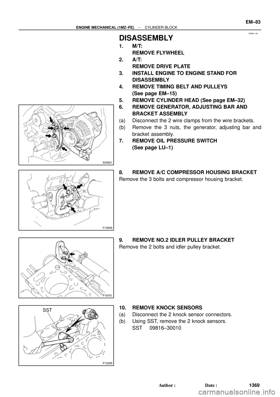
DISASSEMBLY
1. M/T:
REMOVE FLYWHEEL
2. A/T:
REMOVE DRIVE PLATE
3. INSTALL ENGINE TO ENGINE STAND FOR
DISASSEMBLY
4. REMOVE TIMING BELT AND PULLEYS
(See page EM±15)
5. REMOVE CYLINDER HEAD (See page EM±32)
6. REMOVE GENERATOR, ADJUSTING BAR AND
BRACKET ASSEMBLY
(a) Disconnect the 2 wire clamps from the wire brackets.
(b) Remove the 3 nuts, the generator, adjusting bar and
bracket assembly.
7. REMOVE OIL PRESSURE SWITCH
(See page LU±1)
8. REMOVE A/C COMPRESSOR HOUSING BRACKET
Remove the 3 bolts and compressor housing bracket.
9. REMOVE NO.2 IDLER PULLEY BRACKET
Remove the 2 bolts and idler pulley bracket.
10. REMOVE KNOCK SENSORS
(a) Disconnect the 2 knock sensor connectors.
(b) Using SST, remove the 2 knock sensors.
SST 09816±30010