Page 3739 of 4770
B04401
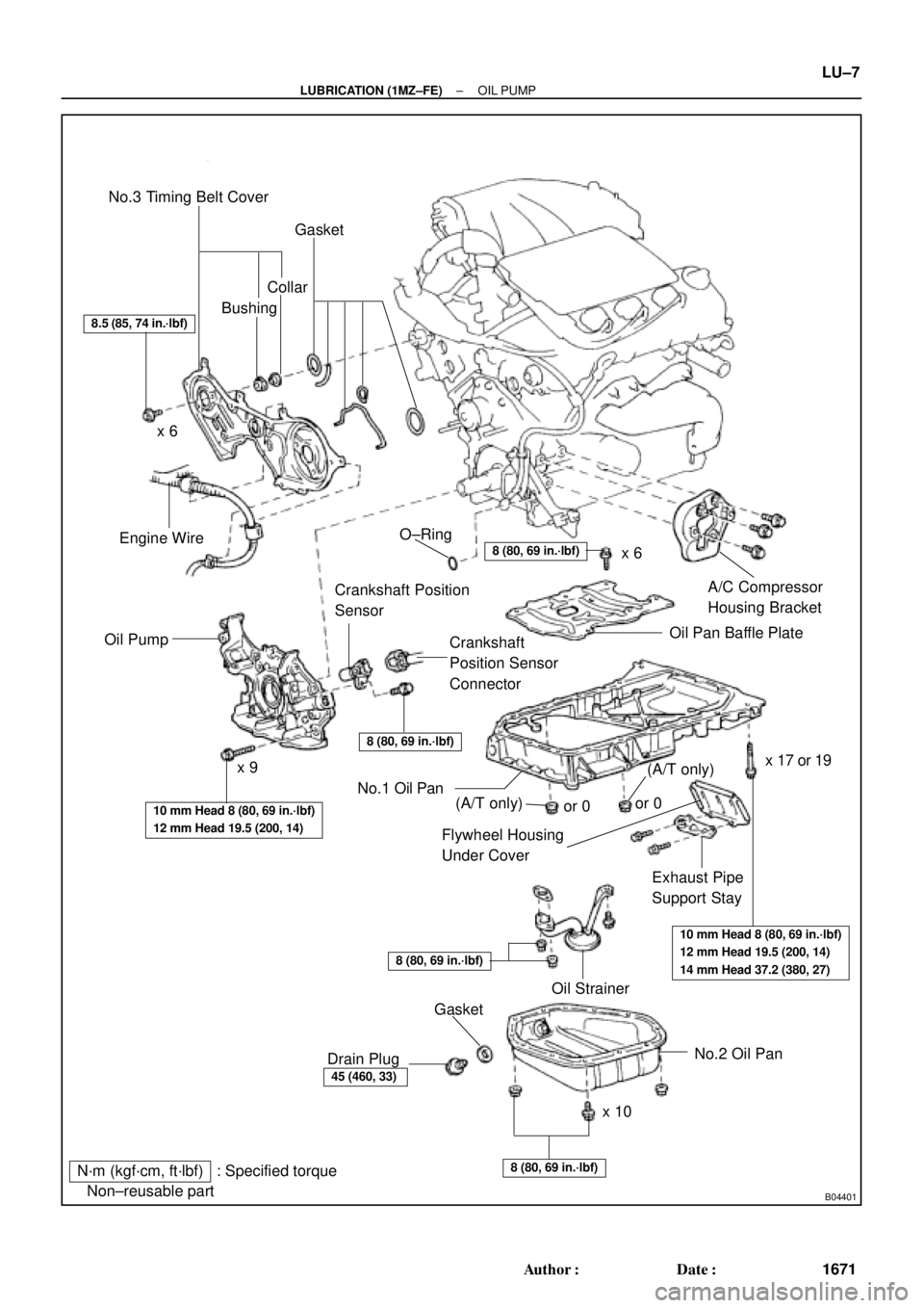
N´m (kgf´cm, ft´lbf) : Specified torque
� Non±reusable partNo.3 Timing Belt Cover
Gasket
BushingCollar
A/C Compressor
Housing Bracket
Oil Pan Baffle Plate
Crankshaft
Position Sensor
Connector Crankshaft Position
Sensor
Oil PumpEngine Wire
Flywheel Housing
Under Cover
Exhaust Pipe
Support Stay
Oil Strainer
No.2 Oil Pan
x 10x 6
x 9� O±Ring
No.1 Oil Pan
� Gasket
Drain Plug
8.5 (85, 74 in.´lbf)
8 (80, 69 in.´lbf)
8 (80, 69 in.´lbf)
10 mm Head 8 (80, 69 in.´lbf)
12 mm Head 19.5 (200, 14)
10 mm Head 8 (80, 69 in.´lbf)
12 mm Head 19.5 (200, 14)
14 mm Head 37.2 (380, 27)
8 (80, 69 in.´lbf)
45 (460, 33)
8 (80, 69 in.´lbf)
x 6
x 17 or 19
(A/T only)(A/T only)or 0or 0
± LUBRICATION (1MZ±FE)OIL PUMP
LU±7
1671 Author�: Date�:
Page 3741 of 4770
LU028±03
P18778Adjusting Bolt
Adjusting
Strut Pivot
Bolt
B01015
P18801
± LUBRICATION (1MZ±FE)OIL PUMP
LU±9
1673 Author�: Date�:
REMOVAL
HINT:
When repairing the oil pump, the oil pan and strainer should be
removed and cleaned.
1. REMOVE RH FRONT WHEEL
2. REMOVE RH FENDER APRON SEAL
3. DRAIN ENGINE OIL
4. REMOVE FRONT EXHAUST PIPE (See page EM±32)
5. REMOVE FRONT EXHAUST PIPE BRACKET FROM
NO.1 OIL PAN
6. REMOVE GENERATOR DRIVE BELT
(See page CH±6)
7. DISCONNECT A/C COMPRESSOR FROM ENGINE
(See page AC±41)
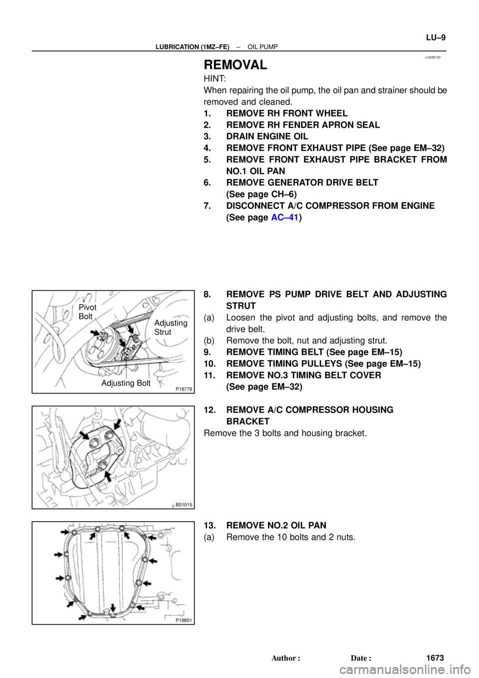
8. REMOVE PS PUMP DRIVE BELT AND ADJUSTING
STRUT
(a) Loosen the pivot and adjusting bolts, and remove the
drive belt.
(b) Remove the bolt, nut and adjusting strut.
9. REMOVE TIMING BELT (See page EM±15)
10. REMOVE TIMING PULLEYS (See page EM±15)
11. REMOVE NO.3 TIMING BELT COVER
(See page EM±32)
12. REMOVE A/C COMPRESSOR HOUSING
BRACKET
Remove the 3 bolts and housing bracket.
13. REMOVE NO.2 OIL PAN
(a) Remove the 10 bolts and 2 nuts.
Page 3750 of 4770
OIL PUMP
1682 Author�: Date�:
(b) Apply seal packing to the No.2 oil pan as shown in the il-
lustration.
Seal packing:
Part No. 08826�")
P12568
A
A
BB
Seal Width
4 ± 5 mm LU±18
± LUBRICATION (1MZ±FE)OIL PUMP
1682 Author�: Date�:
(b) Apply seal packing to the No.2 oil pan as shown in the il-
lustration.
Seal packing:
Part No. 08826±00080 or equivalent
�Install a nozzle that has been cut to a 4 ± 5 mm (0.16
± 0.20 in.) opening.
HINT:
Avoid applying an excessive amount to the surface.
�Parts must be assembled within 3 minutes of ap-
plication. Otherwise the material must be removed
and reapplied.
�Immediately remove nozzle from the tube and rein-
stall cap.
(c) Install the No.2 oil pan with the 10 bolts and 2 nuts. Uni-
formly tighten the bolts and nuts in several passes.
Torque: 8 N´m (80 kgf´cm, 69 in.´lbf)
7. INSTALL A/C COMPRESSOR HOUSING BRACKET
Torque: 25 N´m (250 kgf´cm, 18 ft´lbf)
8. INSTALL NO.3 TIMING BELT COVER
(See page EM±21)
9. INSTALL TIMING PULLEYS (See page EM±21)
10. INSTALL TIMING BELT (See page EM±21)
11. INSTALL ADJUSTING STRUT AND PS PUMP DRIVE
BELT
(a) Temporarily install the adjusting strut with the bolt and the
nut.
(b) Install the drive belt with the pivot and adjusting bolts.
Torque: 43.1 N´m (440 kgf´cm, 32 ft´lbf)
(c) Tighten the nut.
Torque: 43.1 N´m (440 kgf´cm, 32 ft´lbf)
12. INSTALL A/C COMPRESSOR (See page AC±47)
13. INSTALL GENERATOR DRIVE BELT
(See page CH±16)
14. INSTALL FRONT EXHAUST PIPE BRACKET TO
NO.1 OIL PAN
Torque: 21 N´m (210 kgf´cm, 15 ft´lbf)
15. INSTALL FRONT EXHAUST PIPE (See page EM±76)
16. REMOVE RH FENDER APRON SEAL
17. REMOVE RH FRONT WHEEL
18. FILL ENGINE WITH OIL
19. START ENGINE AND CHECK FOR LEAKS
20. RECHECK ENGINE OIL LEVEL
Page 3755 of 4770

1MZ±FE: (See page EM±15)
2. INSPECT DRIVE BELTS
5S±F")
MA00L±01
P00495
Outside
Inside
± MAINTENANCEENGINE
MA±5
48 Author�: Date�:
ENGINE
INSPECTION
1. REPLACE TIMING BELT
5S±FE: (See page EM±17)
1MZ±FE: (See page EM±15)
2. INSPECT DRIVE BELTS
5S±FE: (See page CH±1)
1MZ±FE: (See page CH±1)
3. REPLACE SPARK PLUGS
5S±FE: (See page IG±1)
1MZ±FE: (See page IG±1)
4. INSPECT AIR FILTER
(a) Visually check that the air filter is not excessively dirty or
oily.
(b) Clean the air filter with compressed air.
First blow from the inside thoroughly, then blow off the outside
of the air filter.
5. REPLACE AIR FILTER
Replace the air filter with a new one.
6. REPLACE ENGINE OIL AND OIL FILTER
5S±FE: (See page LU±2)
1MZ±FE: (See page LU±3)
7. REPLACE ENGINE COOLANT
5S±FE: (See page CO±2)
1MZ±FE: (See page CO±2)
8. 1MZ±FE:
INSPECT CHARCOAL CANISTER
(See page EC±6)
9. REPLACE GASKET IN FUEL TANK CAP
5S±FE: (See page EC±6)
1MZ±FE: (See page EC±6)
10. INSPECT FUEL LINES AND CONNECTIONS
5S±FE: (See page EC±6)
1MZ±FE: (See page EC±6)
11. INSPECT EXHAUST PIPES AND MOUNTINGS
5S±FE: (See page EC±15)
1MZ±FE: (See page EC±17)
12. ADJUST VALVE CLEARANCE
5S±FE: (See page EM±4)
1MZ±FE: (See page EM±4)
Page 3854 of 4770
± PREPARATIONENGINE MECHANICAL (5S±FE)
PP±3
55 Author�: Date�:
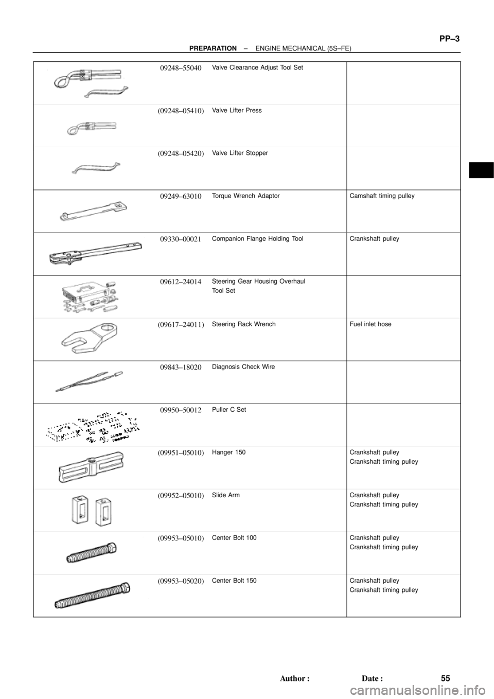
09248±55040Valve Clearance Adjust Tool Set
(09248±05410)Valve Lifter Press
(09248±05420)Valve Lifter Stopper
09249±63010Torque Wrench AdaptorCamshaft timing pulley
09330±00021Companion Flange Holding ToolCrankshaft pulley
09612±24014Steering Gear Housing Overhaul
Tool Set
(09617±24011)Steering Rack WrenchFuel inlet hose
09843±18020Diagnosis Check Wire
09950±50012Puller C Set
(09951±05010)Hanger 150Crankshaft pulley
Crankshaft timing pulley
(09952±05010)Slide ArmCrankshaft pulley
Crankshaft timing pulley
(09953±05010)Center Bolt 100Crankshaft pulley
Crankshaft timing pulley
(09953±05020)Center Bolt 150Crankshaft pulley
Crankshaft timing pulley
Page 3855 of 4770
PP±4
± PREPARATIONENGINE MECHANICAL (5S±FE)
56 Author�: Date�:
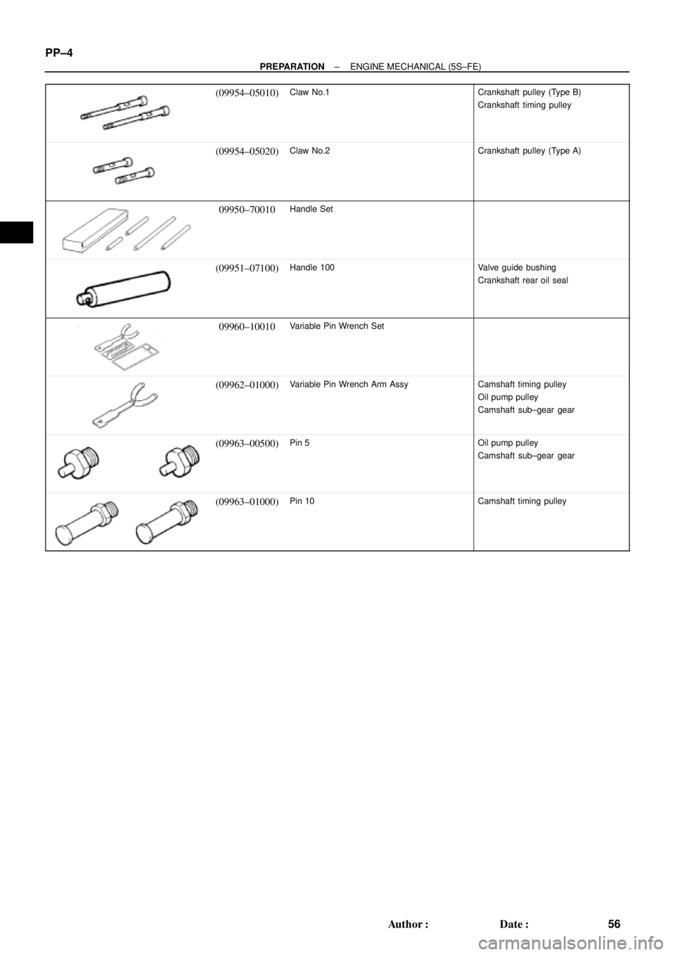
(09954±05010)Claw No.1Crankshaft pulley (Type B)
Crankshaft timing pulley
(09954±05020)Claw No.2Crankshaft pulley (Type A)
09950±70010Handle Set
(09951±07100)Handle 100Valve guide bushing
Crankshaft rear oil seal
09960±10010Variable Pin Wrench Set
(09962±01000)Variable Pin Wrench Arm AssyCamshaft timing pulley
Oil pump pulley
Camshaft sub±gear gear
(09963±00500)Pin 5Oil pump pulley
Camshaft sub±gear gear
(09963±01000)Pin 10Camshaft timing pulley
Page 3859 of 4770
PP0BR±03
PP±8
± PREPARATIONENGINE MECHANICAL (1MZ±FE)
60 Author�: Date�:
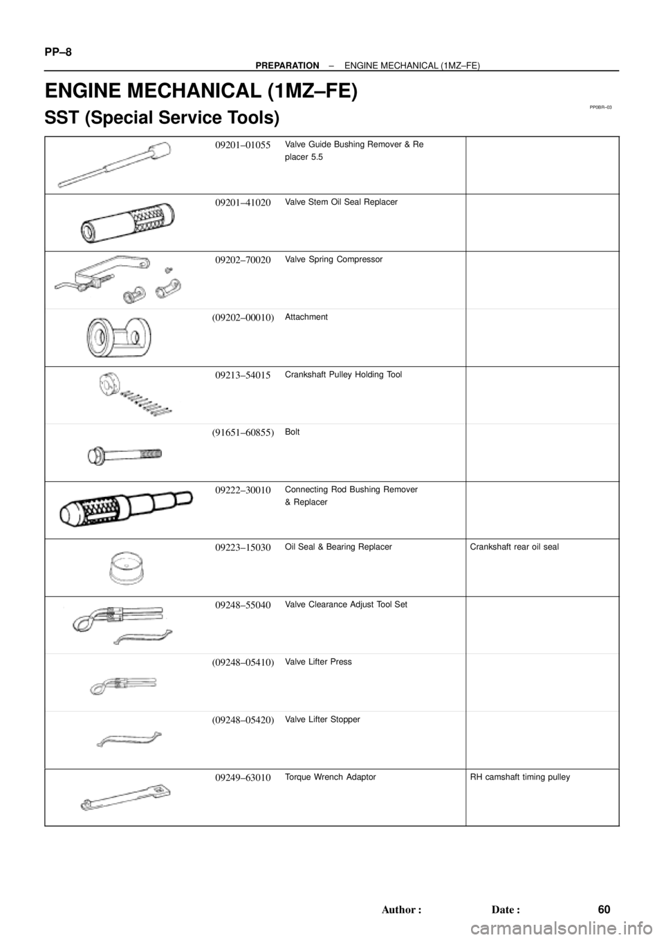
ENGINE MECHANICAL (1MZ±FE)
SST (Special Service Tools)
09201±01055Valve Guide Bushing Remover & Re
placer 5.5
09201±41020Valve Stem Oil Seal Replacer
09202±70020Valve Spring Compressor
(09202±00010)Attachment
09213±54015Crankshaft Pulley Holding Tool
(91651±60855)Bolt
09222±30010Connecting Rod Bushing Remover
& Replacer
09223±15030Oil Seal & Bearing ReplacerCrankshaft rear oil seal
09248±55040Valve Clearance Adjust Tool Set
(09248±05410)Valve Lifter Press
(09248±05420)Valve Lifter Stopper
09249±63010Torque Wrench AdaptorRH camshaft timing pulley
Page 3860 of 4770
± PREPARATIONENGINE MECHANICAL (1MZ±FE)
PP±9
61 Author�: Date�:
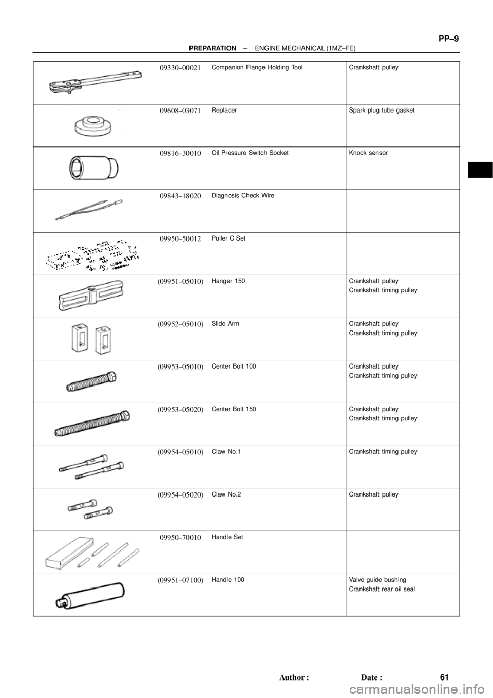
09330±00021Companion Flange Holding ToolCrankshaft pulley
09608±03071ReplacerSpark plug tube gasket
09816±30010Oil Pressure Switch SocketKnock sensor
09843±18020Diagnosis Check Wire
09950±50012Puller C Set
(09951±05010)Hanger 150Crankshaft pulley
Crankshaft timing pulley
(09952±05010)Slide ArmCrankshaft pulley
Crankshaft timing pulley
(09953±05010)Center Bolt 100Crankshaft pulley
Crankshaft timing pulley
(09953±05020)Center Bolt 150Crankshaft pulley
Crankshaft timing pulley
(09954±05010)Claw No.1Crankshaft timing pulley
(09954±05020)Claw No.2Crankshaft pulley
09950±70010Handle Set
(09951±07100)Handle 100Valve guide bushing
Crankshaft rear oil seal