Page 2373 of 4770
CO06O±03
S05950
No.1 Cooling Fan
No.1 Electric Cooling Fan
Upper Radiator HoseNo.1 Electric Cooling Fan Connector
Connector
HolderECT Switch
Connector
ECT Switch
Wire
S05238
Fan
Fan ShroudFan Motor
Connector Holder No.1 Cooling Fan
± COOLING (5S±FE)ELECTRIC COOLING FAN
CO±25
1599 Author�: Date�:
COMPONENTS
Page 2374 of 4770
S05949
No.2 Electric Cooling Fan
Connector
No.2 Electric Cooling Fan No.2 Cooling Fan
S05239
FanConnector Holder
Fan ShroudFan MotorFan Motor Cover No.2 Cooling Fan CO±26
± COOLING (5S±FE)ELECTRIC COOLING FAN
1600 Author�: Date�:
Page 2375 of 4770
CO06P±03
S05956
S05957
± COOLING (5S±FE)ELECTRIC COOLING FAN
CO±27
1601 Author�: Date�:
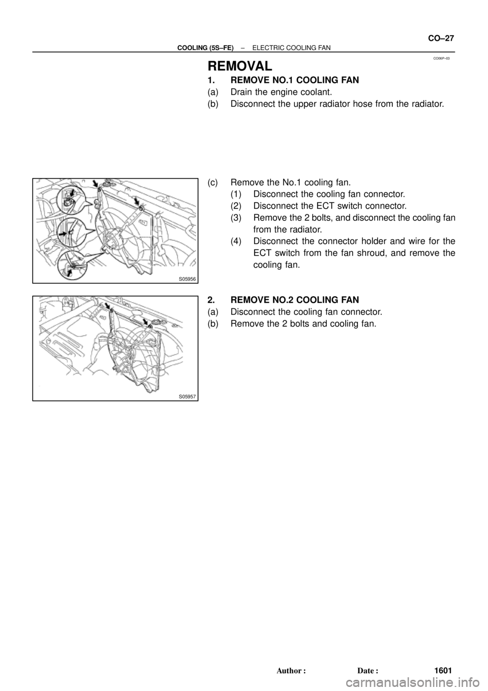
REMOVAL
1. REMOVE NO.1 COOLING FAN
(a) Drain the engine coolant.
(b) Disconnect the upper radiator hose from the radiator.
(c) Remove the No.1 cooling fan.
(1) Disconnect the cooling fan connector.
(2) Disconnect the ECT switch connector.
(3) Remove the 2 bolts, and disconnect the cooling fan
from the radiator.
(4) Disconnect the connector holder and wire for the
ECT switch from the fan shroud, and remove the
cooling fan.
2. REMOVE NO.2 COOLING FAN
(a) Disconnect the cooling fan connector.
(b) Remove the 2 bolts and cooling fan.
Page 2376 of 4770
CO06Q±03
S05234
CO±28
± COOLING (5S±FE)ELECTRIC COOLING FAN
1602 Author�: Date�:
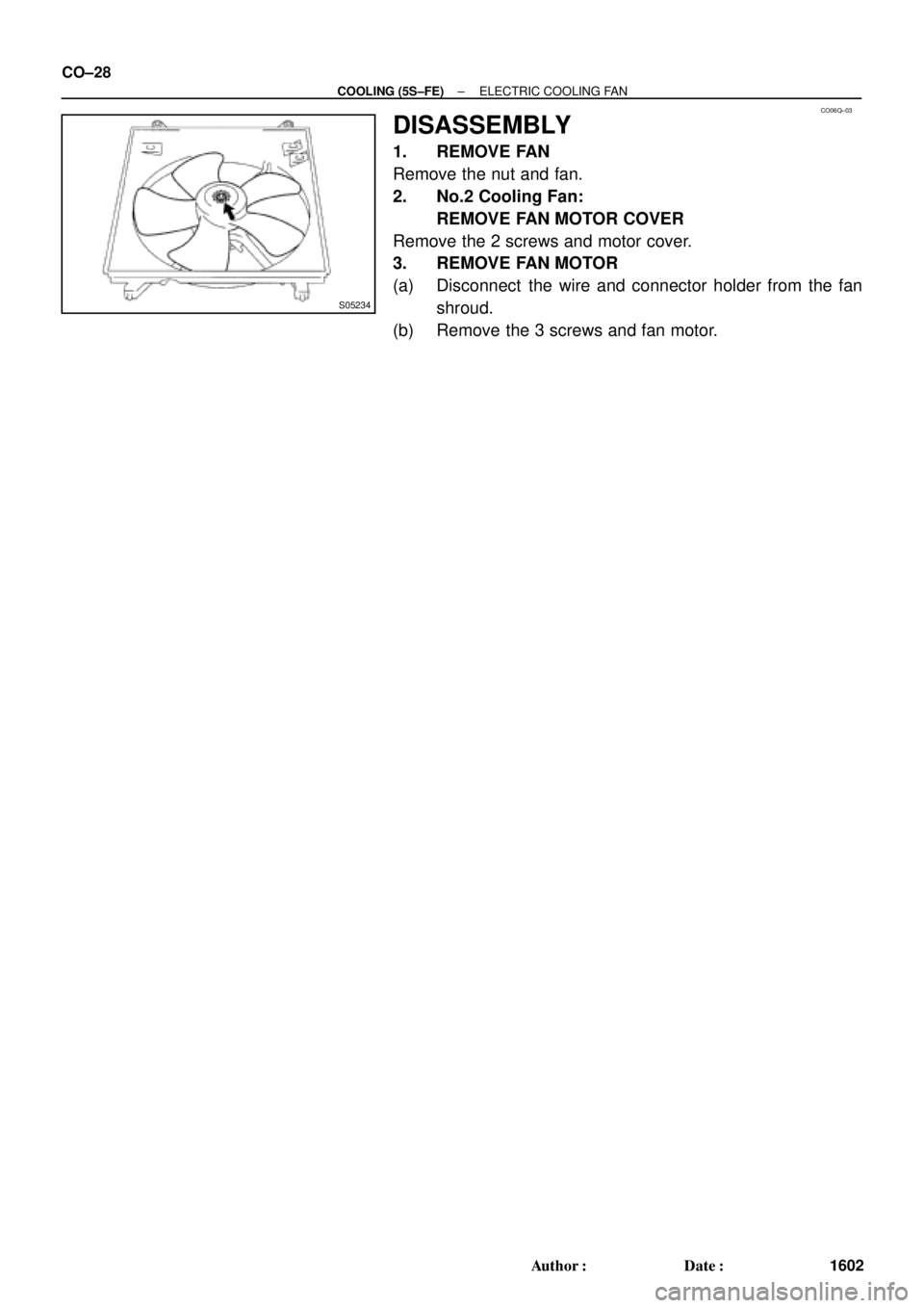
DISASSEMBLY
1. REMOVE FAN
Remove the nut and fan.
2. No.2 Cooling Fan:
REMOVE FAN MOTOR COVER
Remove the 2 screws and motor cover.
3. REMOVE FAN MOTOR
(a) Disconnect the wire and connector holder from the fan
shroud.
(b) Remove the 3 screws and fan motor.
Page 2377 of 4770
CO06R±04
Z19069
No.1 Cooling Fan
No.2 Cooling Fan
± COOLING (5S±FE)ELECTRIC COOLING FAN
CO±29
1603 Author�: Date�:
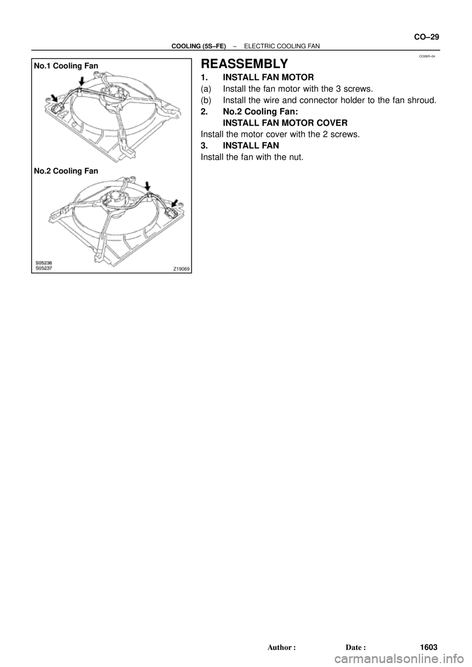
REASSEMBLY
1. INSTALL FAN MOTOR
(a) Install the fan motor with the 3 screws.
(b) Install the wire and connector holder to the fan shroud.
2. No.2 Cooling Fan:
INSTALL FAN MOTOR COVER
Install the motor cover with the 2 screws.
3. INSTALL FAN
Install the fan with the nut.
Page 2378 of 4770
CO06S±03
S06016Attach
S06017Attach CO±30
± COOLING (5S±FE)ELECTRIC COOLING FAN
1604 Author�: Date�:
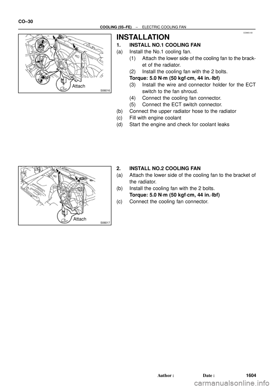
INSTALLATION
1. INSTALL NO.1 COOLING FAN
(a) Install the No.1 cooling fan.
(1) Attach the lower side of the cooling fan to the brack-
et of the radiator.
(2) Install the cooling fan with the 2 bolts.
Torque: 5.0 N´m (50 kgf´cm, 44 in.´lbf)
(3) Install the wire and connector holder for the ECT
switch to the fan shroud.
(4) Connect the cooling fan connector.
(5) Connect the ECT switch connector.
(b) Connect the upper radiator hose to the radiator
(c) Fill with engine coolant
(d) Start the engine and check for coolant leaks
2. INSTALL NO.2 COOLING FAN
(a) Attach the lower side of the cooling fan to the bracket of
the radiator.
(b) Install the cooling fan with the 2 bolts.
Torque: 5.0 N´m (50 kgf´cm, 44 in.´lbf)
(c) Connect the cooling fan connector.
Page 2379 of 4770
CO06T±03
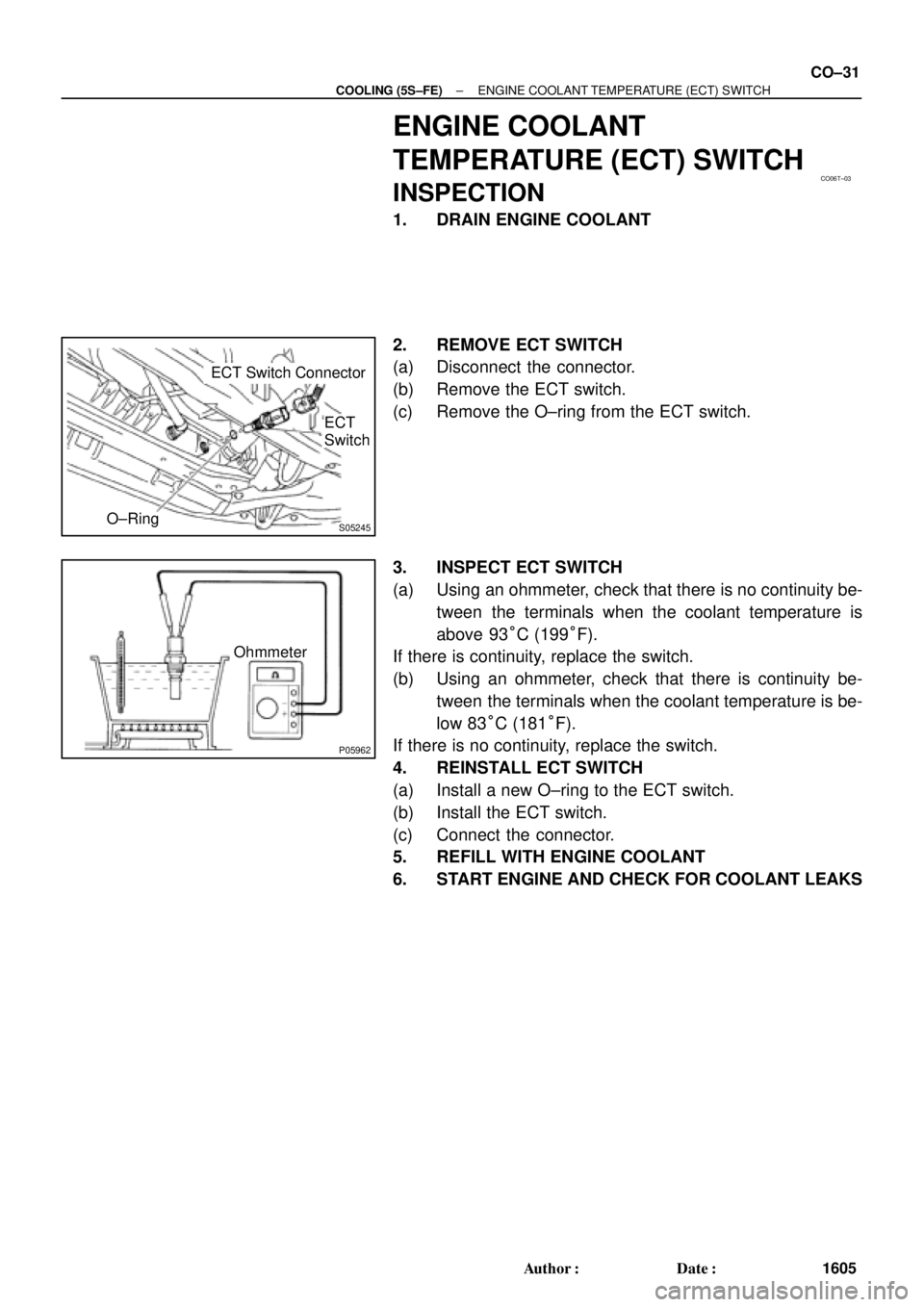
S05245
ECT Switch Connector
O±RingECT
Switch
P05962
Ohmmeter
± COOLING (5S±FE)ENGINE COOLANT TEMPERATURE (ECT) SWITCH
CO±31
1605 Author�: Date�:
ENGINE COOLANT
TEMPERATURE (ECT) SWITCH
INSPECTION
1. DRAIN ENGINE COOLANT
2. REMOVE ECT SWITCH
(a) Disconnect the connector.
(b) Remove the ECT switch.
(c) Remove the O±ring from the ECT switch.
3. INSPECT ECT SWITCH
(a) Using an ohmmeter, check that there is no continuity be-
tween the terminals when the coolant temperature is
above 93°C (199°F).
If there is continuity, replace the switch.
(b) Using an ohmmeter, check that there is continuity be-
tween the terminals when the coolant temperature is be-
low 83°C (181°F).
If there is no continuity, replace the switch.
4. REINSTALL ECT SWITCH
(a) Install a new O±ring to the ECT switch.
(b) Install the ECT switch.
(c) Connect the connector.
5. REFILL WITH ENGINE COOLANT
6. START ENGINE AND CHECK FOR COOLANT LEAKS
Page 2380 of 4770

S05391
Engine
Main Relay
CO06U±03
B02803
Ohmmeter
Continuity
OhmmeterOhmmeter
No Continuity
Continuity21
5
43
B02804
Ohmmeter
Ohmmeter
No Continuity
Continuity 2
1
5
43
Battery
CO±32
± COOLING (5S±FE)ENGINE MAIN RELAY
1606 Author�: Date�:
ENGINE MAIN RELAY
INSPECTION
1. REMOVE RELAY BOX COVER
2. REMOVE ENGINE MAIN RELAY (Marking: ENGINE
MAIN)
3. INSPECT ENGINE MAIN RELAY
(a) Inspect the relay continuity.
(1) Using an ohmmeter, check that there is continuity
between terminals 3 and 5.
If there is no continuity, replace the relay.
(2) Check that there is continuity between terminals 2
and 4.
If there is no continuity, replace the relay.
(3) Check that there is no continuity between terminals
1 and 2.
If there is continuity, replace the relay.
(b) Inspect the relay operation.
(1) Apply battery positive voltage across terminals 3
and 5.
(2) Using an ohmmeter, check that there is no continu-
ity between terminals 2 and 4.
If there is continuity, replace the relay.
(3) Check that there is continuity between terminals 1
and 2.
If there is no continuity, replace the relay.
4. REINSTALL ENGINE MAIN RELAY
5. REINSTALL RELAY BOX COVER

ELECTRIC")