Page 2365 of 4770
S05948
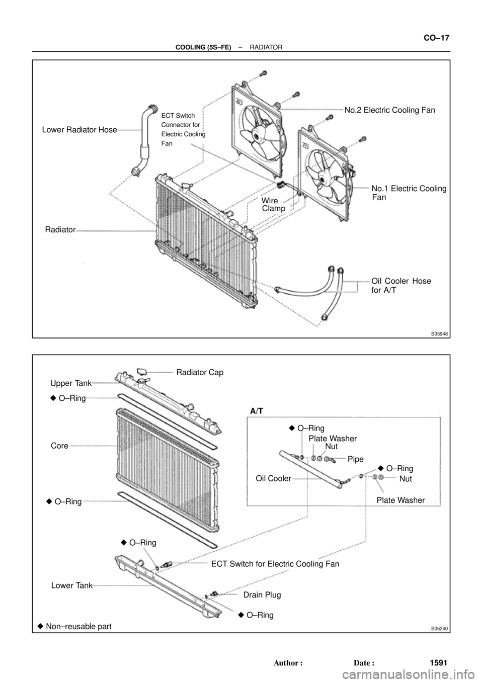
Lower Radiator Hose
RadiatorNo.2 Electric Cooling Fan
No.1 Electric Cooling
Oil Cooler Hose
for A/T
ECT Switch
Connector for
Electric Cooling
Fan
FanWireClamp
S05240
Upper Tank
� O±Ring
Core
Lower Tank
ECT Switch for Electric Cooling Fan
Drain PlugOil Cooler A/T
Pipe
Plate WasherNut
� O±Ring� O±Ring
� O±Ring Radiator Cap
Nut Plate Washer
� Non±reusable part� O±Ring
� O±Ring
± COOLING (5S±FE)RADIATOR
CO±17
1591 Author�: Date�:
Page 2366 of 4770
RADIATOR
1592 Author�: Date�:
REMOVAL
1. DRAIN ENGINE COOLANT
2. REMOVE RADIATOR ASSEMBLY
(a) Disconnect the No.1 electric cooling fan connector.
(b) Disconn")
CO06J±04
S05955
CO±18
± COOLING (5S±FE)RADIATOR
1592 Author�: Date�:
REMOVAL
1. DRAIN ENGINE COOLANT
2. REMOVE RADIATOR ASSEMBLY
(a) Disconnect the No.1 electric cooling fan connector.
(b) Disconnect the No.2 electric cooling fan connector.
(c) Disconnect the ECT switch connector for the electric cool-
ing fan.
(d) Disconnect the upper radiator hose from the radiator.
(e) Disconnect the lower radiator hose from the water inlet.
(f) Disconnect the radiator reservoir hose from the radiator.
(g) A/T:
Disconnect the 2 oil cooler hoses from the oil cooler pipes.
(h) Remove the 2 bolts and 2 upper radiator supports.
(i) Remove the radiator assembly.
(j) Remove the 2 lower radiator supports.
(k) Remove the lower radiator hose from the radiator.
(l) A/T:
Remove the 2 oil cooler hoses from the radiator.
3. REMOVE NO.1 ELECTRIC COOLING FAN FROM RA-
DIATOR
(a) Disconnect the ECT switch connector for the cooling fan.
(b) Disconnect the ECT switch wire clamp for the cooling fan
from the bracket of the radiator.
(c) Remove the 2 bolts and cooling fan.
4. REMOVE NO.2 ELECTRIC COOLING FAN FROM RA-
DIATOR
Remove the 2 bolts and cooling fan.
Page 2367 of 4770
RADIATOR
CO±19
1593 Author�: Date�:
DISASSE")
CO06K±03
CO1205
Dimension ºBº
Overhaul HandleStopper Bolt SSTPart ºAº
Claw
S04699
Stopper
BoltSSTTank
Lock
Plate
S04703
Ta p
S04705
± COOLING (5S±FE)RADIATOR
CO±19
1593 Author�: Date�:
DISASSEMBLY
1. REMOVE ECT SWITCH
(a) Remove the ECT switch.
(b) Remove the O±ring.
2. REMOVE DRAIN PLUG
(a) Remove the drain plug.
(b) Remove the O±ring.
3. ASSEMBLE SST
SST 09230±01010
(a) Install the claw to the overhaul handle, inserting it in the
hole in part ºAº as shown in the diagram.
(b) While gripping the handle, adjust the stopper bolt so that
dimension ºBº is as shown in the illustration.
Dimension: 0.2 ± 0.3 mm (0.008 ± 0.012 in)
NOTICE:
If this adjustment is not done the claw may be damaged.
4. UNCAULK LOCK PLATES
Using SST to release the caulking, squeeze the handle until
stopped by the stopper bolt.
SST 09230±01010
5. REMOVE TANKS AND O±RINGS
Lightly tap the bracket of the radiator (or radiator inlet or outlet)
with a soft±faced hammer, and remove the tank and the O±ring.
6. A/T:
REMOVE OIL COOLER FROM LOWER TANK
(a) Loosen the nut, and remove the cooler pipe.
(b) Remove the 2 nuts and plate washers.
(c) Remove the oil cooler and 2 O±rings.
Page 2368 of 4770
RADIATOR
1594 Author�:")
CO06L±04
S05307
DownwardPipe
18°
CO1267
Lock Plate
CoreLock Plate
CO0317
� Normal
O±RingX Twisted
X Twisted
S04698
Ta pWRONG
CORRECT
Tank
Lock
Plate CO±20
± COOLING (5S±FE)RADIATOR
1594 Author�: Date�:
REASSEMBLY
1. A/T:
INSTALL OIL COOLER TO LOWER TANK
(a) Install 2 new O±rings to the oil cooler.
(b) Install the oil cooler to the lower tank with the 2 plate
washers and nuts.
Torque: 8.3 N´m (85 kgf´cm, 74 in.´lbf)
(c) Install the cooler pipe in the direction indicated in the il-
lustration.
Torque: 14.7 N´m (150 kgf´cm, 11 ft´lbf)
2. INSPECT LOCK PLATE FOR DAMAGE
HINT:
�If the sides of the lock plate groove are deformed, reas-
sembly of the tank will be impossible.
�Therefore, first correct any deformation with pliers or simi-
lar object. Water leakage will result if the bottom of the
lock plate groove is damaged or dented.
NOTICE:
The radiator can only be recaulked 2 times. After the 2nd
time, the radiator core must be replaced.
3. INSTALL NEW O±RINGS AND TANKS
(a) After checking that there are no foreign objects in the lock
plate groove, install the new O±ring without twisting it.
HINT:
When cleaning the lock plate groove, lightly rub it with sand pa-
per without scratching it.
(b) Install the tank without damaging the O±ring.
(c) Tap the lock plate with a soft±faced hammer so that there
is no gap between it and the tank.
Page 2369 of 4770

(3)(3)(3)
(1) (2)
(2)
(2)
(2)
(2) (2) (2)
Z18946
± CO")
CO1206
Dimension ºBº
Stopper Bolt
Overhaul Handle Punch AssemblyPart ºAº
SST
Z18947
5
SST
Stopper
Tank
Lock 1
64
82 7
3
Plate
Bolt
S05241
(1)
(3)(3)(3)
(1) (2)
(2)
(2)
(2)
(2) (2) (2)
Z18946
± COOLING (5S±FE)RADIATOR
CO±21
1595 Author�: Date�:
4. ASSEMBLE SST
SST 09230±01010, 09231±14010
(a) Install the punch assembly to the overhaul handle, insert-
ing it in the hole in part ºAº as shown in the illustration.
(b) While gripping the handle, adjust the stopper bolt so that
dimension ºBº is as shown in the illustration.
Dimension: 8.4 mm (0.331 in)
5. CAULK LOCK PLATE
(a) Lightly press SST against the lock plate in the order
shown in the illustration. After repeating this a few times,
fully caulk the lock plate by squeezing the handle until
stopped by the stopper plate.
SST 09230±01010
HINT:
�Do not stake the areas protruding around the pipes,
brackets or tank ribs.
�The points shown in the illustration and oil cooler near
here (A/T) cannot be staked with the SST. Use pliers or
similar object and be careful not to damage the core
plates.
Page 2370 of 4770
RADIATOR
1596 Author�: Date�:
(b) Check the lock plate height (H) after completing the caulk-
ing.
Plate height: 7.40 ± 7.8")
S04700
H
S04704
SST
S01713
Tank
Lock
O±RingPlate CO±22
± COOLING (5S±FE)RADIATOR
1596 Author�: Date�:
(b) Check the lock plate height (H) after completing the caulk-
ing.
Plate height: 7.40 ± 7.80 mm (0.2913 ± 0.3071 in.)
If not within the specified height, adjust the stopper bolt of the
handle again and caulk again.
6. INSTALL ECT SWITCH
(a) Install a new O±ring to the ECT switch.
(b) Install the ECT switch.
7. INSTALL DRAIN PLUG
(a) Install a new O±ring to the drain plug.
(b) Install the drain plug.
8. INSPECT FOR WATER LEAKS
(a) Plug the inlet and outlet pipes of the radiator with SST.
SST 09230±01010
(b) Using a radiator cap tester, apply pressure to the radiator.
Test pressure: 177 kPa (1.8 kgf/cm
2, 26 psi)
(c) Submerge the radiator in water.
(d) Inspect for leaks.
HINT:
On radiators with resin tanks, there is a clearance between the
tank and lock plate where a minute amount of air will remain,
giving the appearance of an air leak when the radiator is sub-
merged in water. Therefore, before doing the water leak test,
first swish the radiator around in the water until all air bubbles
disappear.
Page 2371 of 4770
RADIATOR
CO±23
1597 Author�: Date�:
INSTALLATION
1. INSTALL NO.1 ELECTRIC COOLING FAN TO RADIA-
TOR
(a) Attach the lower side of the cooling fan to the bracket of")
CO06M±03
S05955
± COOLING (5S±FE)RADIATOR
CO±23
1597 Author�: Date�:
INSTALLATION
1. INSTALL NO.1 ELECTRIC COOLING FAN TO RADIA-
TOR
(a) Attach the lower side of the cooling fan to the bracket of
the radiator.
(b) Install the cooling fan with the 2 bolts.
(c) Connect the ECT switch connector for the cooling fan.
(d) Install the ECT switch wire clamp for the cooling fan to the
bracket of the radiator.
Torque: 5.0 N´m (50 kgf´cm, 44 in.´lbf)
2. INSTALL NO.2 ELECTRIC COOLING FAN TO RADIA-
TOR
(a) Attach the lower side of the cooling fan to the bracket of
the radiator.
(b) Install the cooling fan with the 2 bolts.
Torque: 5.0 N´m (50 kgf´cm, 44 in.´lbf)
3. INSTALL RADIATOR ASSEMBLY
(a) Install the lower radiator hose to the radiator.
(b) A/T:
Install the 2 oil cooler hoses to the radiator.
(c) Install the 2 lower radiator supports to the radiator.
(d) Attach the 2 lower radiator supports on the radiator to the
body brackets.
(e) Install the 2 upper radiator supports with the 2 bolts.
Torque: 12.8 N´m (130 kgf´cm, 9 ft´lbf)
(f) Connect the upper radiator hose to the radiator.
(g) Connect the lower radiator hose to the water inlet.
(h) Connect the radiator reservoir hose to the radiator.
(i) A/T:
Connect the 2 oil cooler hoses to the oil cooler pipes.
(j) Connect the No.1 electric cooling fan connector.
(k) Connect the No.2 electric cooling fan connector.
(l) Connect the ECT switch connector for the electric cooling
fan.
4. FILL WITH ENGINE COOLANT
5. START ENGINE AND CHECK FOR COOLANT LEAKS
Page 2372 of 4770

(+) (+)
(±)
Battery Ammeter CO±24
± COOLING (5S±FE)ELECTRIC COOLING FAN
1598 Author�: Date�:
ELECTRIC COOLING FAN")
S05959
CO06N±03
S05953
ECT Switch
Connector
Z19282
No.1
No.2Battery
Ammeter (±)
(+) (+)
(±)
Battery Ammeter CO±24
± COOLING (5S±FE)ELECTRIC COOLING FAN
1598 Author�: Date�:
ELECTRIC COOLING FAN
ON±VEHICLE INSPECTION
1. CHECK COOLING FAN OPERATION WITH LOW TEM-
PERATURE (Below 83°C (181°F))
(a) Turn the ignition switch ON.
(b) Check that the cooling fan stops.
If not, check the cooling fan relay and ECT switch, and check
for a separated connector or severed wire between the cooling
fan relay and ECT switch.
(c) Disconnect the ECT switch connector.
(d) Check that the cooling fan rotates.
If not, check the fan main relay, cooling fan relay, cooling fan,
fuses, and check for short circuit between the cooling fan relay
and ECT switch.
(e) Reconnect the ECT switch connector.
2. CHECK COOLING FAN OPERATION WITH HIGH TEM-
PERATURE (Above 93°C (199°F))
(a) Start the engine, and raise coolant temperature to above
93°C (199°F).
(b) Check that the cooling fan rotates.
If not, replace the ECT switch.
3. INSPECT COOLING FANS
(a) Disconnect the cooling fan connector.
(b) Connect battery and ammeter to the connector.
(c) Check that the cooling fan rotates smoothly, and check
the reading on the ammeter.
Standard amperage: 4.9 ± 8.5 A
(d) Reconnect the cooling fan connector.