Page 1529 of 4770

I01390
Condition: Insufficient cooling
I01392
Condition: Insufficient cooling
NOTE : These gauge indica-
tions are shown when the
refrigeration system has
been opened and the refrig-
erant charged without vacu-
um purging.
± AIR CONDITIONINGAIR CONDITIONING SYSTEM
AC±7
2489 Author�: Date�:
(6) Refrigerant overcharged or insufficient cooling of
condenser
Symptom seen in
refrigeration systemProbable causeDiagnosisRemedy
� Pressure too high on both low
and high pressure sides
� No air bubbles seen through the
sight glass even when the engine
rpm is lowered� Unable to develop sufficient per-
formance due to excessive refrig-
eration system
� Insufficient cooling of condenser� Excessive refrigerant in
cycle " refrigerant over charged
� Condenser cooling " condenser
fins clogged of condenser fan
faulty
(1) Clean condenser
(2) Check condenser fan motor
operation
(3) If (1) and (2) are in normal
state, check amount of refrigerant
Charge proper amount of refriger-
ant
(7) Air present in refrigeration system
Symptom seen in
refrigeration systemProbable causeDiagnosisRemedy
� Pressure too high on both low
and high pressure sides
� The low pressure piping hot to
touch
� Bubbles seen in sight glass
Air entered in refrigeration system
� Air present in refrigeration sys-
tem
� Insufficient vacuum purging
(1) Check compressor oil to see if
it is dirty or insufficient
(2) Evacuate air and charge new
refrigerant
Page 1530 of 4770
I01450
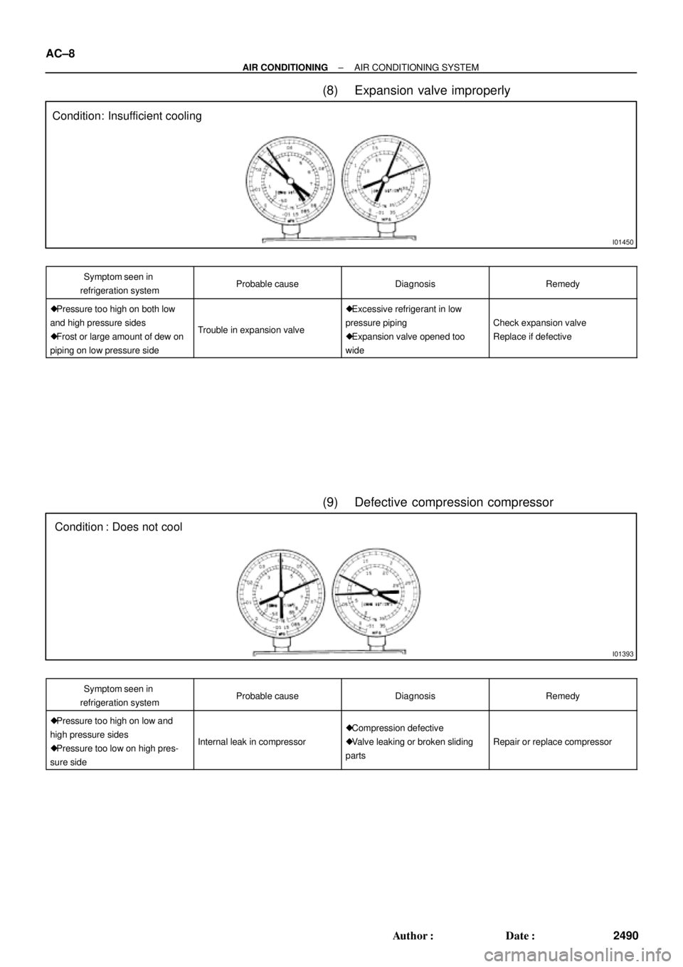
Condition: Insufficient cooling
I01393
Condition : Does not cool AC±8
± AIR CONDITIONINGAIR CONDITIONING SYSTEM
2490 Author�: Date�:
(8) Expansion valve improperly
Symptom seen in
refrigeration systemProbable causeDiagnosisRemedy
� Pressure too high on both low
and high pressure sides
� Frost or large amount of dew on
piping on low pressure side
Trouble in expansion valve
� Excessive refrigerant in low
pressure piping
� Expansion valve opened too
wide
Check expansion valve
Replace if defective
(9) Defective compression compressor
Symptom seen in
refrigeration systemProbable causeDiagnosisRemedy
� Pressure too high on low and
high pressure sides
� Pressure too low on high pres-
sure side
Internal leak in compressor
� Compression defective
� Valve leaking or broken sliding
parts
Repair or replace compressor
Page 1531 of 4770
 Warm up engine.
(b) Inspect idle±up speed when the these conditions are es-
tablished.
�Warm up en")
± AIR CONDITIONINGAIR CONDITIONING SYSTEM
AC±9
2491 Author�: Date�:
3. INSPECT IDLE±UP SPEED
(a) Warm up engine.
(b) Inspect idle±up speed when the these conditions are es-
tablished.
�Warm up engine
�Blower speed control switch at ºHIº position
�A/C switch ON
�Temperature control dial at ºCOOLº position
Magnetic clutch conditionIdle±up speed
Magnetic clutch not engaged700 ± 50 rpm
Magnetic clutch engaged700 ± 50 rpm
If idle speed is not as specified, check ISC valve and air intake
system.
4. INSPECT FOR LEAKAGE OF REFRIGERANT
(a) Perform in these conditions:
�Stop engine.
�Secure good ventilation (If not the gas leak detector
may react to volatile gases witch are not refrigerant,
such as evaporated gasoline and exhaust gas.)
�Repeat the test 2 or 3 times.
�Make sure that there is some refrigerant remaining
in the refrigeration system.
When compressor is OFF: approx. 392 ± 588 kPa
(4 ± 6 kgf/ cm
2, 57 ± 85 psi)
(b) Bring the gas leak detector close to the drain hose before
performing the test.
HINT:
�After the blower motor stopped, leave the cooling unit for
more than 15 minutes.
�Expose the gas leak detector sensor the under the drain
hose.
�When bring the gas leak detector close to the drain hose,
make sure that the gas leak detector does not react to the
volatile gases.
If such reaction is unavoidable, the vehicle must be lifted up.
(c) If gas leak is not detected on the drain hose, remove the
blower resistor from the cooling unit. Then insert the gas
leak detector sensor into the unit and perform the test.
(d) Disconnect the connector and leave the pressure switch
for approx. 20 minutes. Then bring the gas leak detector
close to the pressure switch and perform the test.
(e) Bring the gas leak detector close to the refrigerant lines
and perform the test.
Page 1535 of 4770
AC0LL±02
Z19146
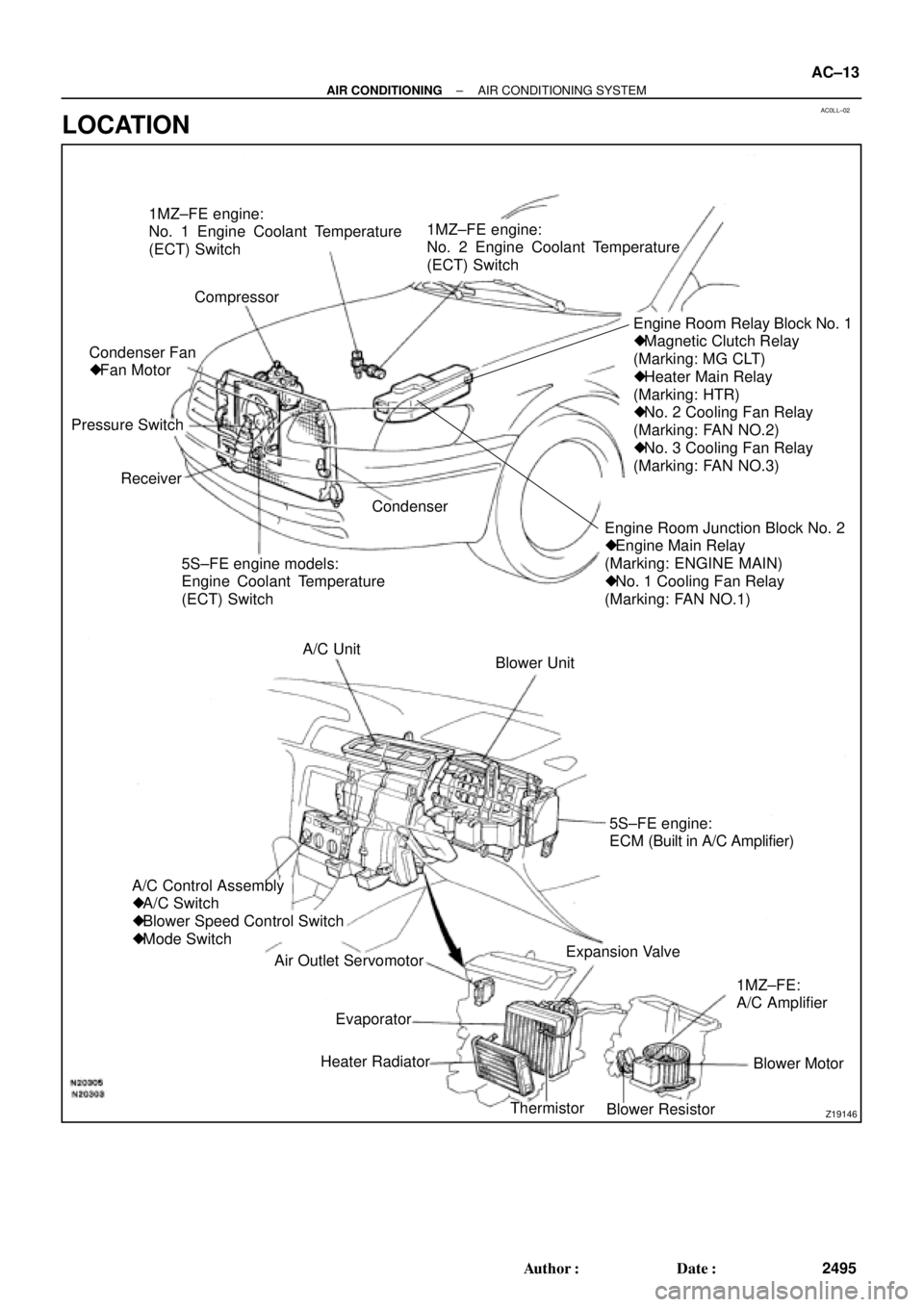
1MZ±FE engine:
No. 1 Engine Coolant Temperature
(ECT) Switch
Compressor
Engine Room Junction Block No. 2
� Engine Main Relay
(Marking: ENGINE MAIN)
� No. 1 Cooling Fan Relay
(Marking: FAN NO.1)Engine Room Relay Block No. 1
� Magnetic Clutch Relay
(Marking: MG CLT)
� Heater Main Relay
(Marking: HTR)
� No. 2 Cooling Fan Relay
(Marking: FAN NO.2)
� No. 3 Cooling Fan Relay
(Marking: FAN NO.3)
5S±FE engine models:
Engine Coolant Temperature
(ECT) Switch Receiver Pressure SwitchCondenser Fan
� Fan Motor1MZ±FE engine:
No. 2 Engine Coolant Temperature
(ECT) Switch
Condenser
Blower Unit A/C Unit
A/C Control Assembly
� A/C Switch
� Blower Speed Control Switch
� Mode Switch
Air Outlet Servomotor
Heater Radiator
Thermistor
Blower ResistorBlower Motor 1MZ±FE:
A/C Amplifier Expansion Valve5S±FE engine:
ECM (Built in A/C Amplifier)
Evaporator
± AIR CONDITIONINGAIR CONDITIONING SYSTEM
AC±13
2495 Author�: Date�:
LOCATION
Page 1537 of 4770

± AIR CONDITIONINGTROUBLESHOOTING
AC±15
2497 Author�: Date�:
Cool air comes out only at high engine rpm
1. Refrigerant volume
2. Drive belt
3. Magnetic clutch
4. Compressor
5. Condenser
6. Condenser fan
7. Receiver
8. Expansion valve
9. Evaporator
10.Thermistor
11. Refrigerant line
12.Pressure switch
13.*
1 ECM
*2 A/C amplifier
AC±3
AC±16
AC±16
AC±39
AC±52
AC±74
AC±49
AC±59
AC±30
AC±24
AC±21
AC±67
DI±218
AC±88
No engine idle±up when A/C switch ON
1. *1 ECM
*2 A/C amplifier
2. Wire harness
DI±218
AC±88
±
Blinking of A/C indicator
1. *1 ECM
*2 A/C amplifier
2. Thermistor
3. Compressor
DI±218
AC±88
AC±24
AC±39
A/C indicator does not lights up when turn mode switch to DEF.
position
1. A/C Fuse
2. Mode switch
3. A/C switch
4. *
1 ECM
*2 A/C amplifier
5. Wire harness
±
AC±84
AC±84
DI±218
AC±88
±
No warm air comes out
1. Engine coolant volume
2. A/C control assembly
3. Heater radiator±
AC±80
AC±57
No condenser fan operation
1. CDS FAN Fuse
2. Engine main relay
3. Cooling fan relay No. 1
4. Cooling fan relay No. 2
5. Cooling fan relay No. 3
6. Condenser fan motor
7. Pressure switch
8. *
1 Engine coolant temp. switch
*2 No. 1 Engine coolant temp. switch
9. *2No. 2 Engine coolant temp. switch
10.Wire harness
±
±
AC±72
AC±72
AC±72
AC±74
AC±67
AC±92
AC±92
AC±92
±
*1: 5S±FE Engine Models
*
2: 1MZ±FE Engine Models
Page 1594 of 4770
S05390
No. 1 Cooling
Fan Relay
AC226±01
S05387
No. 2 Cooling
Fan Relay
S05388
No. 3 Cooling
Fan Relay
Z12319
1
3
24
1
2 34
N23635
5 1 42
3 AC±72
± AIR CONDITIONINGCOOLING FAN RELAY
2554 Author�: Date�:
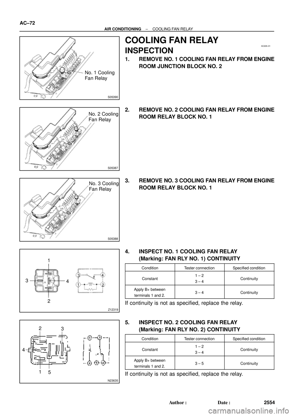
COOLING FAN RELAY
INSPECTION
1. REMOVE NO. 1 COOLING FAN RELAY FROM ENGINE
ROOM JUNCTION BLOCK NO. 2
2. REMOVE NO. 2 COOLING FAN RELAY FROM ENGINE
ROOM RELAY BLOCK NO. 1
3. REMOVE NO. 3 COOLING FAN RELAY FROM ENGINE
ROOM RELAY BLOCK NO. 1
4. INSPECT NO. 1 COOLING FAN RELAY
(Marking: FAN RLY NO. 1) CONTINUITY
ConditionTester connectionSpecified condition
Constant1 ± 2
3 ± 4Continuity
Apply B+ between
terminals 1 and 2.3 ± 4Continuity
If continuity is not as specified, replace the relay.
5. INSPECT NO. 2 COOLING FAN RELAY
(Marking: FAN RLY NO. 2) CONTINUITY
ConditionTester connectionSpecified condition
Constant1 ± 2
3 ± 4Continuity
Apply B+ between
terminals 1 and 2.3 ± 5Continuity
If continuity is not as specified, replace the relay.
Page 1595 of 4770
Z18060
12 3
5
12 3
5
± AIR CONDITIONINGCOOLING FAN RELAY
AC±73
2555 Author�: Date�:
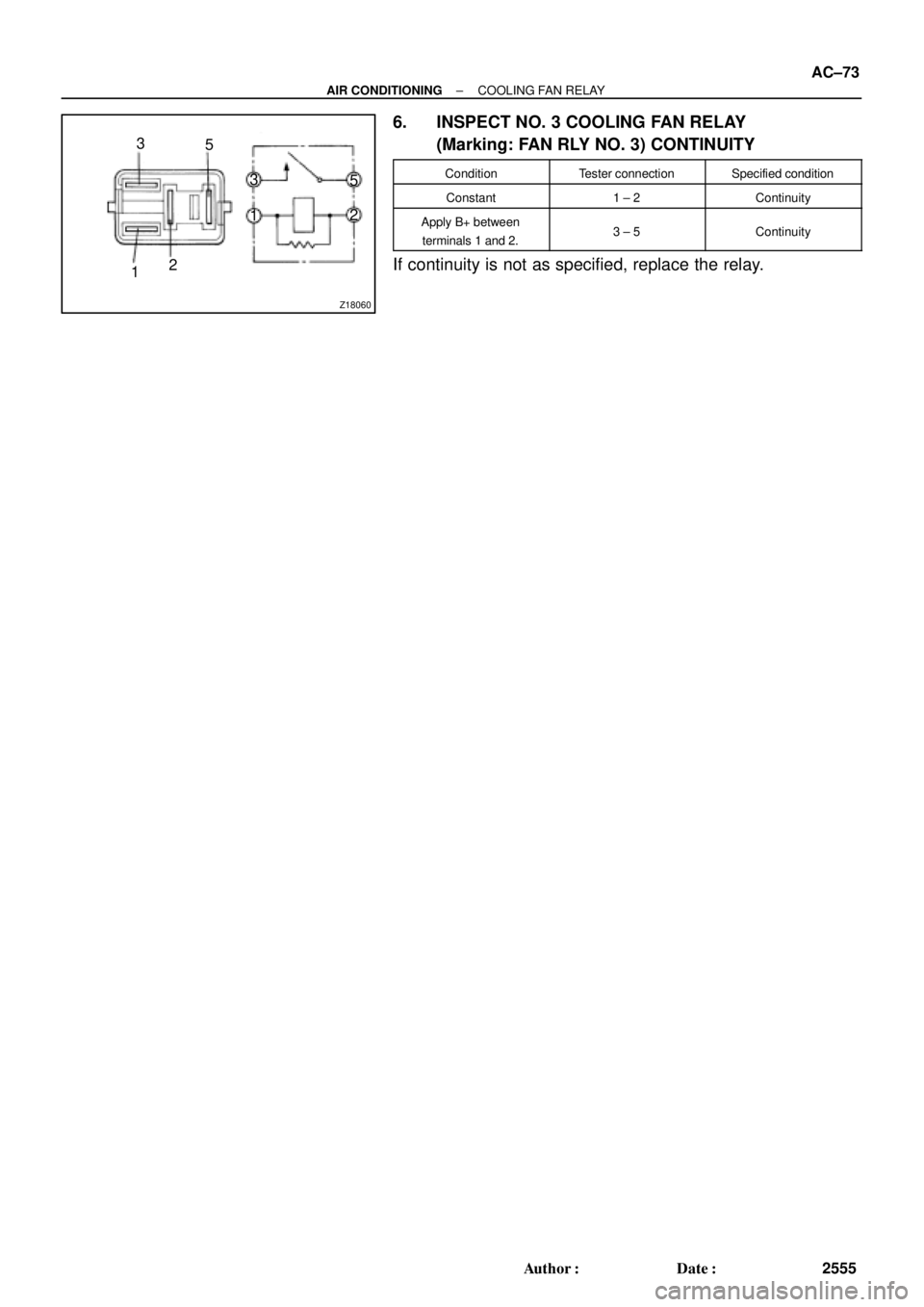
6. INSPECT NO. 3 COOLING FAN RELAY
(Marking: FAN RLY NO. 3) CONTINUITY
ConditionTester connectionSpecified condition
Constant1 ± 2Continuity
Apply B+ between
terminals 1 and 2.3 ± 5Continuity
If continuity is not as specified, replace the relay.
Page 1596 of 4770

AC0N6±02
N20290
21
A AC±74
± AIR CONDITIONINGCONDENSER FAN
2556 Author�: Date�:
CONDENSER FAN
ON±VEHICLE INSPECTION
1. INSPECT CONDENSER FAN OPERATION
Inspect the fan operation, as shown in the chart below.
Test conditions:
�Ignition switch ON
�Blower speed control switch position ºHIº
�A/C switch ON
ConditionFan operation (Fan speed)
Engine coolant temperature
83°C (181°F) or belowNot rotate
Engine coolant temperature
98°C (208°F) or aboveRotate
Refrigerant pressure is less than
1,520 kPa (15.5 kgf/cm2, 220 psi)Not rotate (Low Speed)
Refrigerant pressure is 1,520 kPa
(15.5 kgf/cm2, 220 psi) or aboveRotate (High Speed)
If operation is not as specified, proceed next inspection.
2. INSPECT CONDENSER FAN MOTOR OPERATION
(a) Disconnect the fan connector.
(b) Connect the battery and ammeter to the connector, as
shown in the illustation.
(c) Check that the fan rotates smoothly, and then check that
the reading on the ammeter.
Specified amperage: 10.1 ± 1.8 A at 20 °C (68 °F)
�If operation is not as specified, replace the fan mo-
tor.
�If operation is as specified, check the pressure
switch, cooling fan relays and engine coolant temp.
switch.