Page 2357 of 4770
± COOLING (5S±FE)WATER PUMP
CO±9
1583 Author�: Date�:
6. INSTALL TIMING BELT TENSION SPRING
(See page EM±23)
7. CONNECT LOWER RADIATOR HOSE TO WATER IN-
LET
8. INSTALL TIMING BELT (See page EM±23)
9. FILL WITH ENGINE COOLANT
10. START ENGINE AND CHECK FOR COOLANT LEAKS
Page 2358 of 4770
CO06C±03
S05299
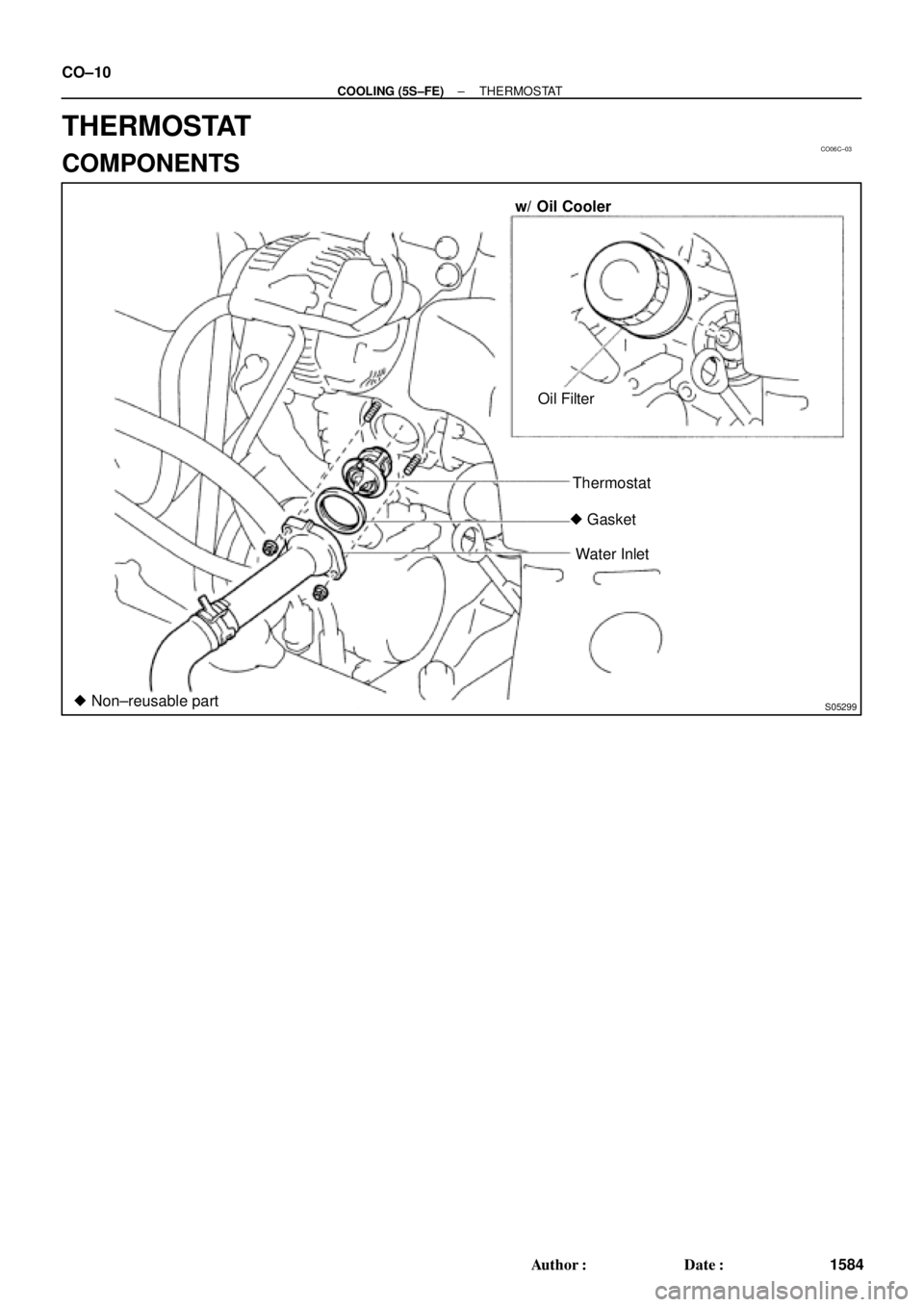
w/ Oil Cooler
Oil Filter
Thermostat
� Gasket
Water Inlet
� Non±reusable part CO±10
± COOLING (5S±FE)THERMOSTAT
1584 Author�: Date�:
THERMOSTAT
COMPONENTS
Page 2359 of 4770
CO06D±03
S05322
± COOLING (5S±FE)THERMOSTAT
CO±11
1585 Author�: Date�:
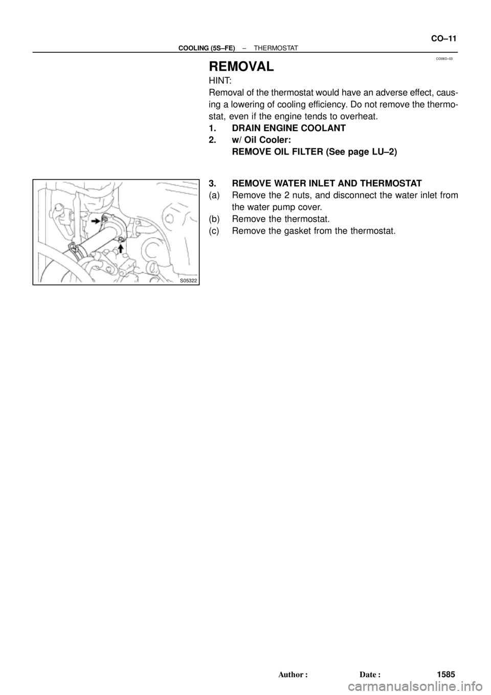
REMOVAL
HINT:
Removal of the thermostat would have an adverse effect, caus-
ing a lowering of cooling efficiency. Do not remove the thermo-
stat, even if the engine tends to overheat.
1. DRAIN ENGINE COOLANT
2. w/ Oil Cooler:
REMOVE OIL FILTER (See page LU±2)
3. REMOVE WATER INLET AND THERMOSTAT
(a) Remove the 2 nuts, and disconnect the water inlet from
the water pump cover.
(b) Remove the thermostat.
(c) Remove the gasket from the thermostat.
Page 2360 of 4770
CO06E±03
P13560
P00436
P24125
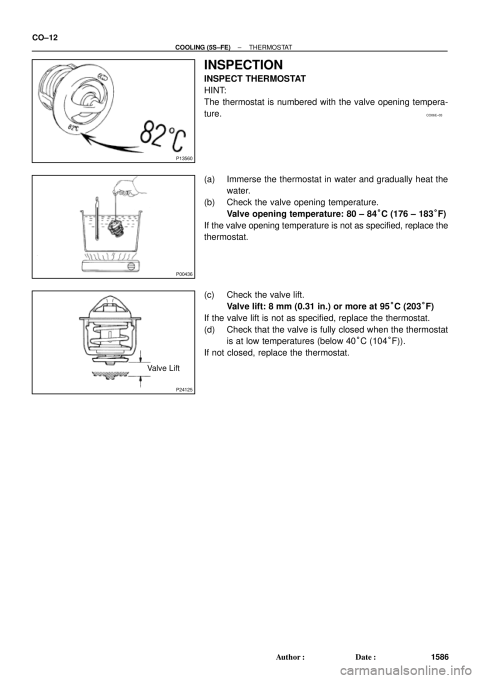
Valve Lift CO±12
± COOLING (5S±FE)THERMOSTAT
1586 Author�: Date�:
INSPECTION
INSPECT THERMOSTAT
HINT:
The thermostat is numbered with the valve opening tempera-
ture.
(a) Immerse the thermostat in water and gradually heat the
water.
(b) Check the valve opening temperature.
Valve opening temperature: 80 ± 84°C (176 ± 183°F)
If the valve opening temperature is not as specified, replace the
thermostat.
(c) Check the valve lift.
Valve lift: 8 mm (0.31 in.) or more at 95°C (203°F)
If the valve lift is not as specified, replace the thermostat.
(d) Check that the valve is fully closed when the thermostat
is at low temperatures (below 40°C (104°F)).
If not closed, replace the thermostat.
Page 2361 of 4770
CO0SN±01
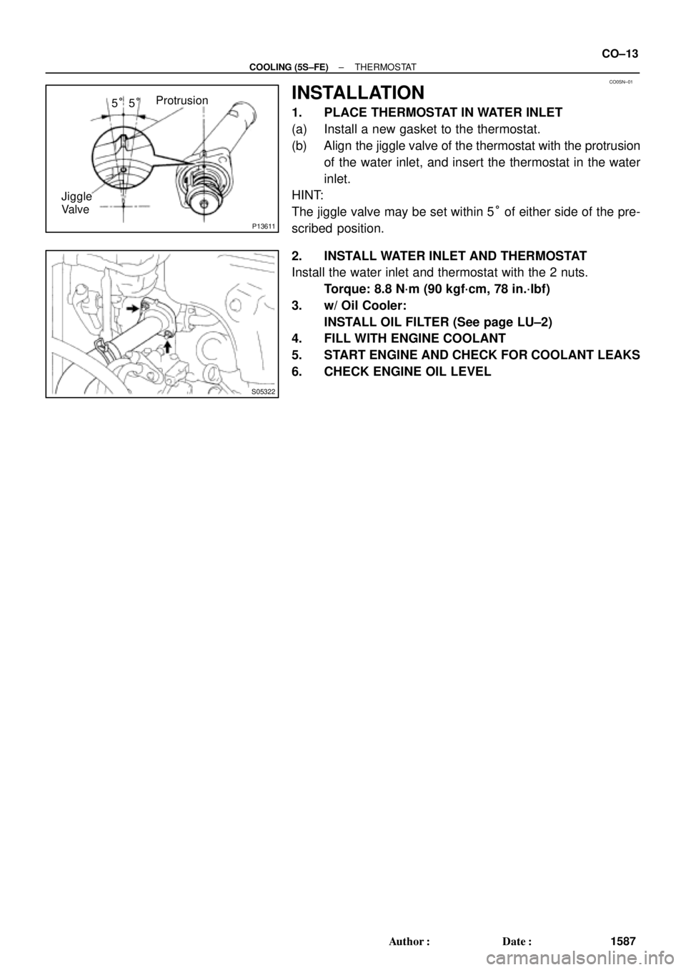
P13611
Protrusion
Jiggle
Valve5°5°
S05322
± COOLING (5S±FE)THERMOSTAT
CO±13
1587 Author�: Date�:
INSTALLATION
1. PLACE THERMOSTAT IN WATER INLET
(a) Install a new gasket to the thermostat.
(b) Align the jiggle valve of the thermostat with the protrusion
of the water inlet, and insert the thermostat in the water
inlet.
HINT:
The jiggle valve may be set within 5° of either side of the pre-
scribed position.
2. INSTALL WATER INLET AND THERMOSTAT
Install the water inlet and thermostat with the 2 nuts.
Torque: 8.8 N´m (90 kgf´cm, 78 in.´lbf)
3. w/ Oil Cooler:
INSTALL OIL FILTER (See page LU±2)
4. FILL WITH ENGINE COOLANT
5. START ENGINE AND CHECK FOR COOLANT LEAKS
6. CHECK ENGINE OIL LEVEL
Page 2362 of 4770
CO06G±03
CO±14
± COOLING (5S±FE)RADIATOR
1588 Author�: Date�:
RADIATOR
ON±VEHICLE CLEANING
Using water or a steam cleaner, remove any mud or dirt from the radiator core.
NOTICE:
If using a high pressure type cleaner, be careful not to deform the fins of the radiator core. (i.e. Main-
tain a distance between the cleaner nozzle and radiator core.)
Page 2363 of 4770
RADIATOR
CO±15
1589 Author�: Date�:
ON±VEHICLE INSPECTION
1. REMOVE RADIATOR CAP
CAUTION:")
CO06H±04
Z00570
30° or More
Radiator CapRadiator Cap Tester
B06362
Radiator Cap Tester
± COOLING (5S±FE)RADIATOR
CO±15
1589 Author�: Date�:
ON±VEHICLE INSPECTION
1. REMOVE RADIATOR CAP
CAUTION:
To avoid the danger of being burned, do not remove the ra-
diator cap while the engine and radiator are still hot, as fluid
and steam can be blown out under pressure.
2. INSPECT RADIATOR CAP
NOTICE:
�If the radiator cap has contaminations, always rinse
it with water.
�Before using a radiator cap tester, wet the relief valve
and pressure valve with engine coolant or water.
�When performing steps (a) and (b) below, keep the
tester at an angle of over 30° above the horizontal.
(a) Using a radiator cap tester, slowly pump the tester and
check that air is coming from the vacuum valve.
Pump speed: 1 push/(3 seconds or more)
NOTICE:
Push the pump at a constant speed.
If air is not coming from the vacuum valve, replace the radiator
cap.
(b) Pump the tester, and measure the relief valve opening
pressure.
Pump speed: 1 push within 1 second
NOTICE:
This pump speed is for the first pump only (in order to close
the vacuum valve). After this, the pump speed can be re-
duced.
Standard opening pressure:
74 ± 103 kPa (0.75 ± 1.05 kgf/cm
2, 10.7 ± 14.9 psi)
Minimum opening pressure:
59 kPa (0.6 kgf/cm
2, 8.5 psi)
HINT:
Use the tester's maximum reading as the opening pressure.
If the opening pressure is less than minimum, replace the radia-
tor cap.
3. INSPECT COOLING SYSTEM FOR LEAKS
(a) Fill the radiator with coolant, and attach a radiator cap tes-
ter.
(b) Warm up the engine.
(c) Pump it to 118 kPa (1.2 kgf/cm
2, 17.1 psi), and check that
the pressure does not drop.
If the pressure drops, check the hoses, radiator or water pump
for leaks. If no external leaks are found, check the heater core,
cylinder block and head.
4. REINSTALL RADIATOR CAP
Page 2364 of 4770
CO06I±03
S05951
No.2 Electric
Cooling Fan
Connector
Radiator Assembly
Lower Radiator
Support
Lower Radiator Hose
Upper Radiator Hose
Oil Cooler Hose for A/TUpper Radiator Support
No.1 Electric Cooling Fan Connector
ECT Switch Connector
for Electric Cooling Fan Upper Radiator Support Radiator Reservoir Hose CO±16
± COOLING (5S±FE)RADIATOR
1590 Author�: Date�:
COMPONENTS