Page 2397 of 4770
P13014
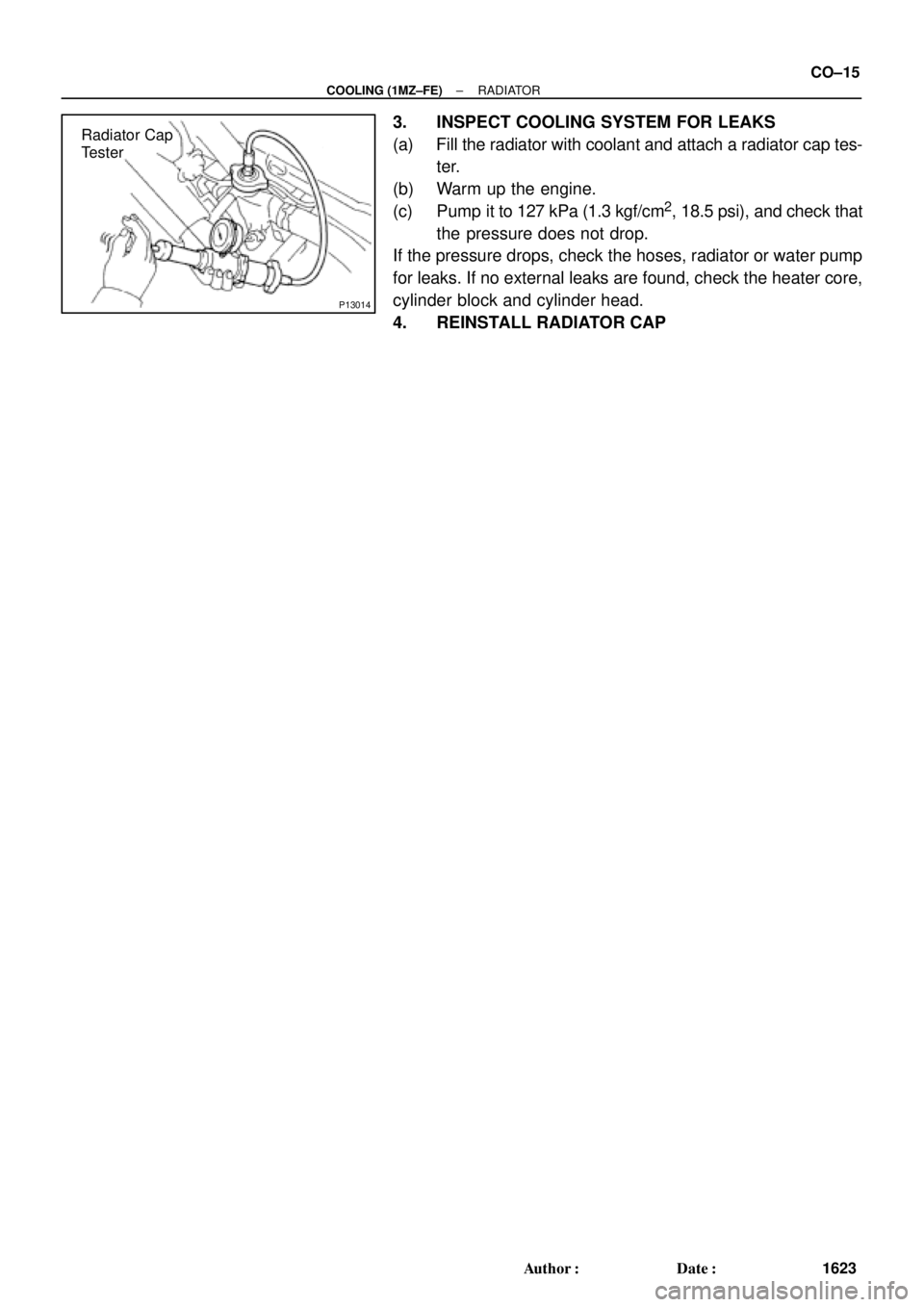
Radiator Cap
Tester
± COOLING (1MZ±FE)RADIATOR
CO±15
1623 Author�: Date�:
3. INSPECT COOLING SYSTEM FOR LEAKS
(a) Fill the radiator with coolant and attach a radiator cap tes-
ter.
(b) Warm up the engine.
(c) Pump it to 127 kPa (1.3 kgf/cm
2, 18.5 psi), and check that
the pressure does not drop.
If the pressure drops, check the hoses, radiator or water pump
for leaks. If no external leaks are found, check the heater core,
cylinder block and cylinder head.
4. REINSTALL RADIATOR CAP
Page 2398 of 4770
CO03N±03
B06399
Radiator
No.1 ECT Switch
No.2 Cooling Fan Connector
Upper Radiator Support Upper Radiator Hose
No.1 Cooling Fan Connector
No.1 ECT Switch Wire Connector Radiator Assembly
Lower Radiator
Support� O±Ring
A/T Oil Cooler Hose
Relay Block
(for Daytime Running Light System) No.1 ECT Switch Wire No.1 Cooling FanNo.2 Cooling Fan
Upper Radiator Support
Lower Radiator
Support
� Non±reusable part� O±Ring Drain PlugLower
Radiator
Hose A/T Oil Cooler Hose
Lower Radiator Hose CO±16
± COOLING (1MZ±FE)RADIATOR
1624 Author�: Date�:
COMPONENTS
Page 2399 of 4770
S04606
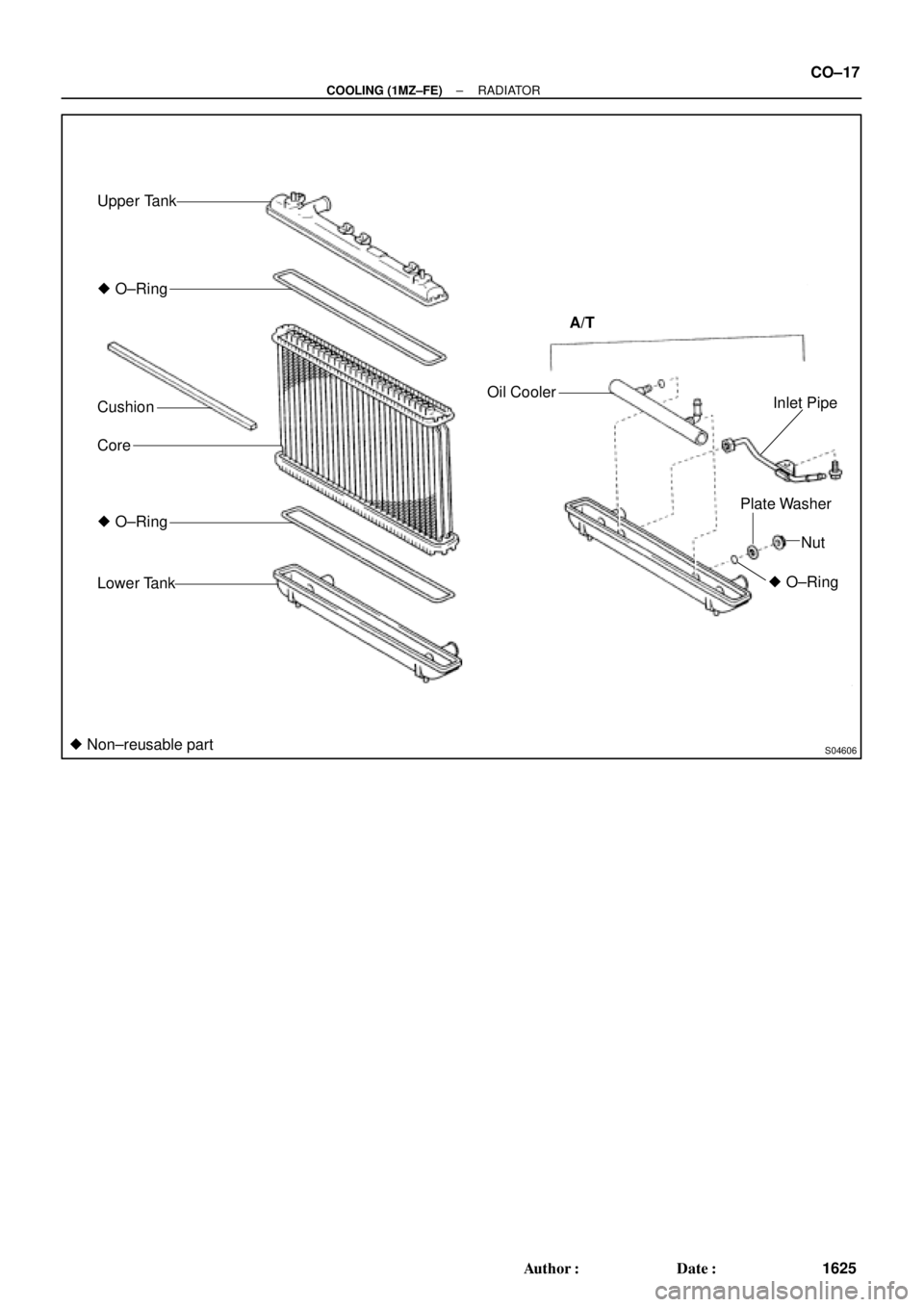
Upper Tank
Lower Tank � O±Ring
Cushion
CoreOil Cooler
Inlet Pipe
Plate Washer
Nut A/T
� Non±reusable part� O±Ring
� O±Ring
± COOLING (1MZ±FE)RADIATOR
CO±17
1625 Author�: Date�:
Page 2400 of 4770
RADIATOR
1626 Author�: Date�:
REMOVAL
HINT:
�At the time of installation, please refer to the following
items.
�Start the")
CO03O±03
S04725
B05937
Lower
Hose
Oil
Cooler
Hose
CO±18
± COOLING (1MZ±FE)RADIATOR
1626 Author�: Date�:
REMOVAL
HINT:
�At the time of installation, please refer to the following
items.
�Start the engine, and check for coolant and A/T fluid
leaks.
�Check the A/T fluid level. (See page DI±438)
1. DRAIN ENGINE COOLANT
2. CANADA:
DISCONNECT RELAY BLOCK (FOR DAYTIME
RUNNING LIGHT SYSTEM) FROM BATTERY
HOLD±DOWN CLAMP
3. DISCONNECT UPPER RADIATOR HOSE FROM
RADIATOR
4. DISCONNECT LOWER RADIATOR HOSE FROM
WATER INLET PIPE
5. DISCONNECT A/T OIL COOLER HOSES FROM OIL
COOLER PIPES
6. DISCONNECT NO.1 AND NO.2 COOLING FAN
CONNECTORS
7. DISCONNECT NO.1 ECT SWITCH WIRE CONNECTOR
8. REMOVE RADIATOR AND COOLING FANS
ASSEMBLY
(a) Remove the 2 bolts and 2 upper supports.
Torque: 12.8 N´m (130 kgf´cm, 9 ft´lbf)
(b) Lift out the radiator, and remove the radiator and cooling
fans assembly.
(c) Remove the 2 lower supports.
9. REMOVE A/T OIL COOLER HOSES FROM
RADIATOR
10. REMOVE LOWER RADIATOR HOSE FROM
RADIATOR
Page 2401 of 4770
S04588
B05938
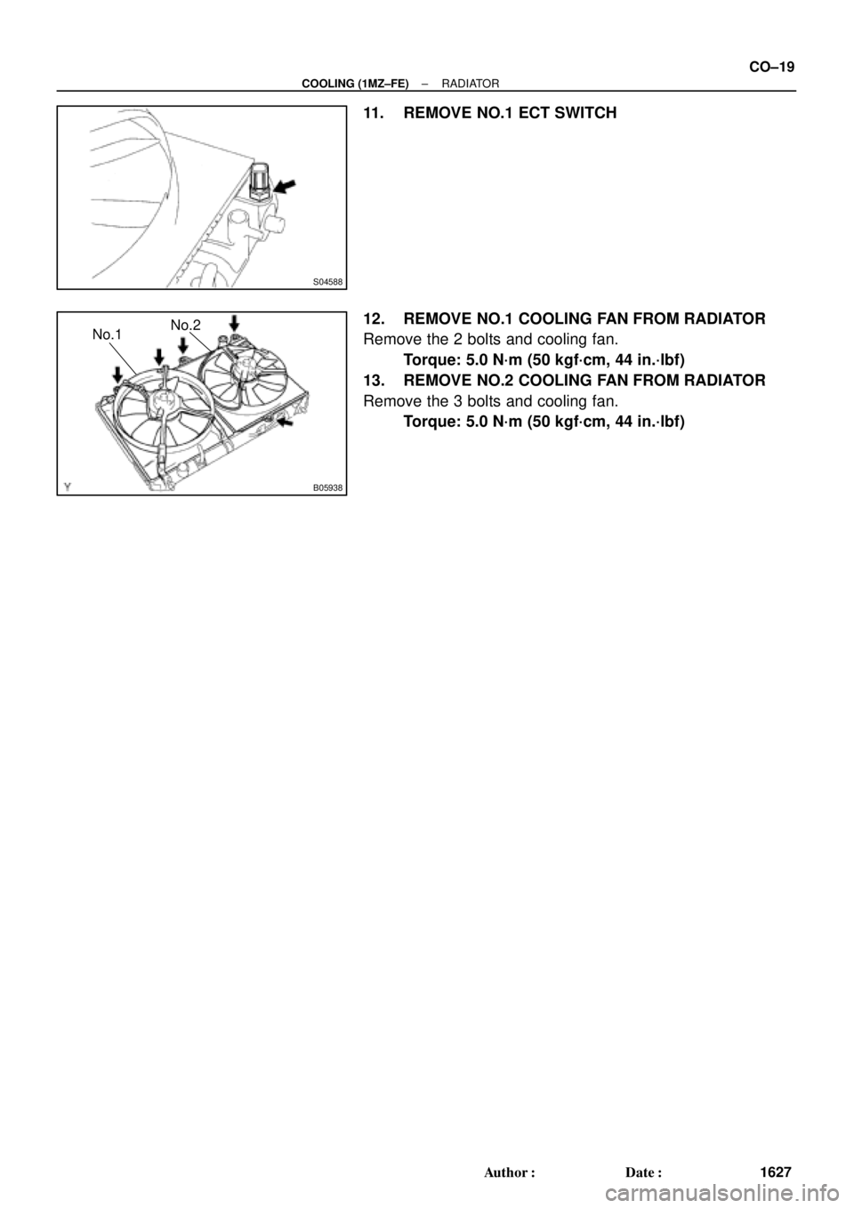
No.1No.2
± COOLING (1MZ±FE)RADIATOR
CO±19
1627 Author�: Date�:
11. REMOVE NO.1 ECT SWITCH
12. REMOVE NO.1 COOLING FAN FROM RADIATOR
Remove the 2 bolts and cooling fan.
Torque: 5.0 N´m (50 kgf´cm, 44 in.´lbf)
13. REMOVE NO.2 COOLING FAN FROM RADIATOR
Remove the 3 bolts and cooling fan.
Torque: 5.0 N´m (50 kgf´cm, 44 in.´lbf)
Page 2402 of 4770
RADIATOR
1628 Author�: Date�:
DISA")
CO03P±03
CO1205Overhaul HandleStopper Bolt Dimension ºBº
ClawPart ºAº
SST
S04737Stopper BoltLock Plate
SSTTank
S04738
Ta p
Z18546
A/T CO±20
± COOLING (1MZ±FE)RADIATOR
1628 Author�: Date�:
DISASSEMBLY
1. REMOVE CUSHION FROM RADIATOR
2. ASSEMBLE SST
SST 09230±01010
(a) Install the claw to the overhaul handle, inserting it in the
hole in part ºAº as shown in the diagram.
(b) While gripping the handle, adjust the stopper bolt so that
dimension ºBº shown in the diagram is 0.2 ± 0.5 mm
(0.008 ± 0.020 in.).
NOTICE:
If this adjustment is not done, the claw may be damaged.
3. UNCAULK LOCK PLATES
Using SST to release the caulking, squeeze the handle until
stopped by the stopper bolt.
SST 09230±01010
4. REMOVE TANKS AND O±RINGS
(a) Lightly tap the bracket of the radiator (or radiator hose in-
let or outlet) with a soft±faced hammer and remove the
tank.
(b) Remove the O±ring.
5. A/T:
REMOVE OIL COOLER FROM LOWER TANK
(a) Remove the pipe.
(b) Remove the nuts and plate washers.
(c) Remove the oil cooler and O±rings.
Page 2403 of 4770

(2)
(3)(4)(5) (6)
CO1267
Lock Plate
Lock Plate
Core
CO0317
O±Ring� Normal
X Twisted
X Twisted
± COOLING (1MZ±FE)RADIATOR
CO±21
1629 Author�: Date�:
REASSEMBLY
1. A/T:
INST")
CO03Q±03
Z18506
A/T
(1)
(2)
(3)(4)(5) (6)
CO1267
Lock Plate
Lock Plate
Core
CO0317
O±Ring� Normal
X Twisted
X Twisted
± COOLING (1MZ±FE)RADIATOR
CO±21
1629 Author�: Date�:
REASSEMBLY
1. A/T:
INSTALL OIL COOLER TO LOWER TANK
(a) Clean the O±ring contact surface of the lower tank and oil
cooler.
(b) Install a new O±rings (1) to the oil cooler (2).
(c) Install the oil cooler with the O±rings to the lower tank (3).
(d) Install the plate washers (4), and nuts (5). Torque the
nuts.
Torque: 8.3 N´m (85 kgf´cm, 74 in.´lbf)
(e) Install the pipe (6).
Torque: 14.7 N´m (150 kgf´cm, 11 ft´lbf)
2. INSPECT LOCK PLATE
Inspect the lock plate for damage.
HINT:
�If the sides of the lock plate groove are deformed, reas-
sembly of the tank will be impossible.
�Therefore, first correct any deformation with pliers or simi-
lar object. Water leakage will result if the bottom of the
lock plate groove is damaged or dented, Therefore, repair
or replace if necessary.
NOTICE:
The radiator can only be recaulked 2 times. After the 2nd
time, the radiator core must be replaced.
3. INSTALL NEW O±RINGS AND TANKS
(a) After checking that there are no foreign objects in the lock
plate groove, install the new O±ring without twisting it.
HINT:
When cleaning the lock plate groove, lightly rub it with sand pa-
per without scratching it.
Page 2404 of 4770

S04736
Ta pCORRECT
WRONGTank
Lock
Plate
CO1206
Dimension ºBº
Stopper Bolt Part ºAº
Punch Assembly Overhaul HandleSST
S04739
13
2 5
47
68
Stopper
BoltSST
Tank
Lock
Plate
S04734
Rib
Bracket CO±22
± COOLING (1MZ±FE)RADIATOR
1630 Author�: Date�:
(b) Install the tank without damaging the O±ring.
(c) Tap the lock plate with a soft±faced hammer so that there
is no gap between it and the tank.
4. ASSEMBLE SST
SST 09230±01010, 09231±14010
(a) Install the punch assembly to the overhaul handle, insert-
ing it in the hole in part ºAº as shown in the illustration.
(b) While gripping the handle, adjust the stopper bolt so that
dimension ºBº shown in the diagram.
Dimension ºBº: 8.4 mm (0.34 in.)
5. CAULK LOCK PLATE
(a) Lightly press SST against the lock plate in the order
shown in the illustration. After repeating this a few times,
fully caulk the lock plate by squeezing the handle until
stopped by the stopper plate.
SST 09230±01010
HINT:
�Do not stake the areas protruding around the pipes,
brackets or tank ribs.