Page 2405 of 4770
S04726
S04735
H
± COOLING (1MZ±FE)RADIATOR
CO±23
1631 Author�: Date�: �
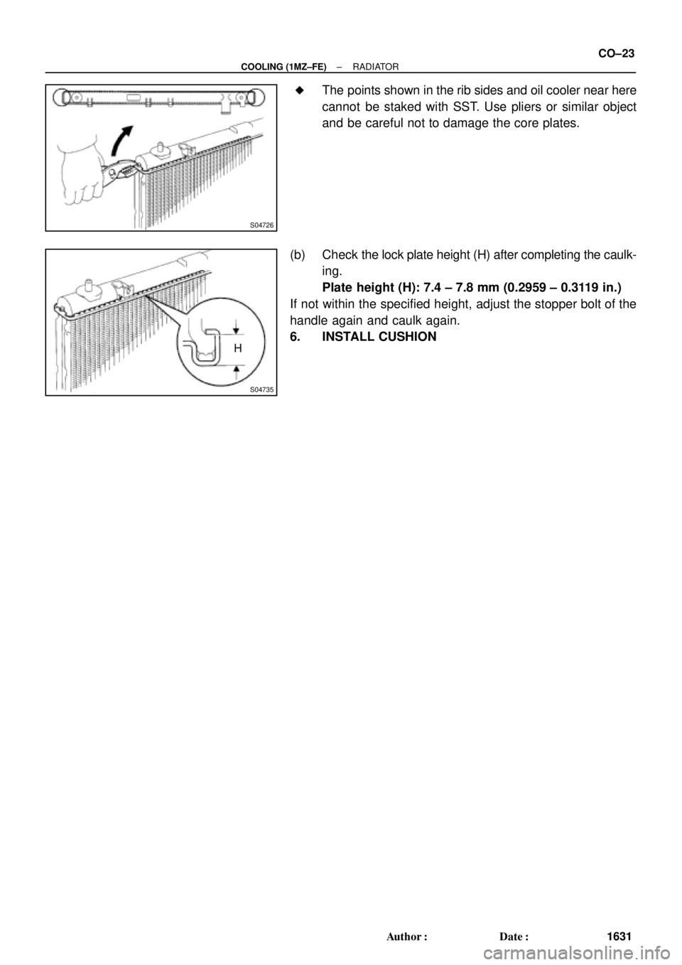
The points shown in the rib sides and oil cooler near here
cannot be staked with SST. Use pliers or similar object
and be careful not to damage the core plates.
(b) Check the lock plate height (H) after completing the caulk-
ing.
Plate height (H): 7.4 ± 7.8 mm (0.2959 ± 0.3119 in.)
If not within the specified height, adjust the stopper bolt of the
handle again and caulk again.
6. INSTALL CUSHION
Page 2406 of 4770
CO03R±01
CO±24
± COOLING (1MZ±FE)RADIATOR
1632 Author�: Date�:
INSTALLATION
Installation is in the reverse order of removal. (See page CO±18)
Page 2407 of 4770
ELECTRIC COOLING FAN
CO±25
1633 Author�: Date�:
ELECTRIC COOLING FAN
ON±VEHICLE INSPECTION
1. CHECK COOLING FAN O")
B05939
CO03S±03
S04727
Disconnect
B05940
B05941
Ammeter
Battery
± COOLING (1MZ±FE)ELECTRIC COOLING FAN
CO±25
1633 Author�: Date�:
ELECTRIC COOLING FAN
ON±VEHICLE INSPECTION
1. CHECK COOLING FAN OPERATION WITH LOW
TEMPERATURE (Below 88°C (190°F))
(a) Turn the ignition switch ON.
(b) Check that the cooling fan stops.
If not, check the cooling fan relay and ECT switch, and check
for a separated connector or severed wire between the cooling
fan relay and ECT switch.
(c) Disconnect the No.1 ECT switch connector.
(d) Check that the cooling fan rotates.
If not, check the fuses, engine main relay, cooling fan relay,
cooling fan, and check for a short circuit between the cooling
fan relay and ECT switch.
(e) Reconnect the No.1 ECT switch connector.
2. CHECK COOLING FAN OPERATION WITH HIGH
TEMPERATURE (Above 98°C (208°F))
(a) Start the engine, and raise coolant temperature to above
98°C (208°F).
(b) Check that the cooling fan rotates.
If not, replace the No.1 ECT switch.
3. INSPECT NO.1 COOLING FAN
(a) Disconnect the cooling fan connector.
(b) Connect battery and ammeter to the cooling fan connec-
tor.
(c) Check that the cooling fan rotates smoothly, and check
the reading on the ammeter.
Standard amperage: 8.3 ± 11.3 A at 20°C (68°F)
(d) Reconnect the cooling fan connector.
Page 2408 of 4770
B05942
Ammeter
Battery CO±26
± COOLING (1MZ±FE)ELECTRIC COOLING FAN
1634 Author�: Date�:
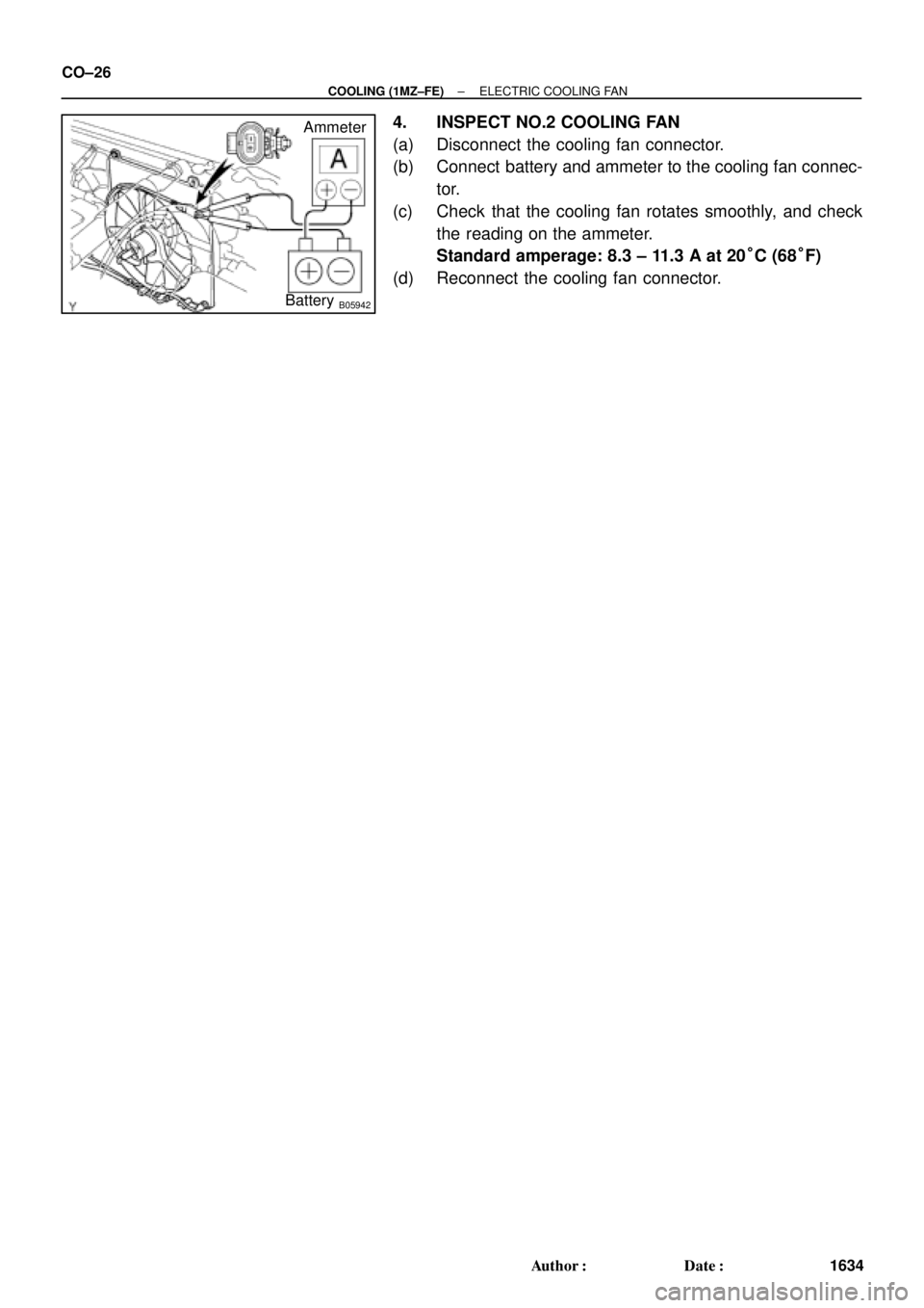
4. INSPECT NO.2 COOLING FAN
(a) Disconnect the cooling fan connector.
(b) Connect battery and ammeter to the cooling fan connec-
tor.
(c) Check that the cooling fan rotates smoothly, and check
the reading on the ammeter.
Standard amperage: 8.3 ± 11.3 A at 20°C (68°F)
(d) Reconnect the cooling fan connector.
Page 2409 of 4770
CO03T±03
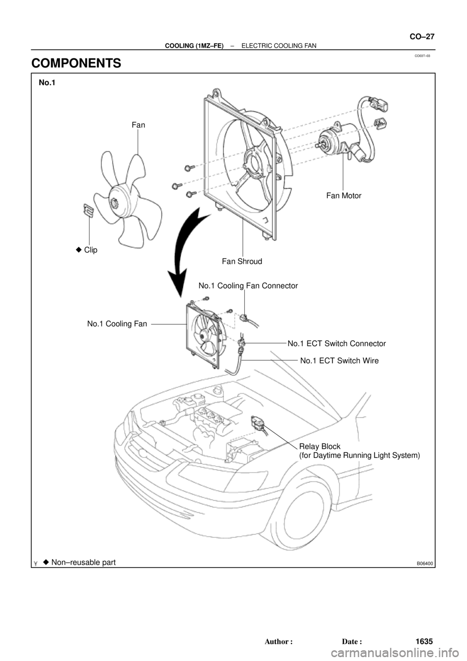
B06400
No.1 Cooling FanNo.1 Cooling Fan Connector
No.1 ECT Switch Connector
No.1 ECT Switch Wire
Relay Block
(for Daytime Running Light System)
� Non±reusable part� ClipFan
Fan ShroudFan Motor
No.1
± COOLING (1MZ±FE)ELECTRIC COOLING FAN
CO±27
1635 Author�: Date�:
COMPONENTS
Page 2410 of 4770
B06402
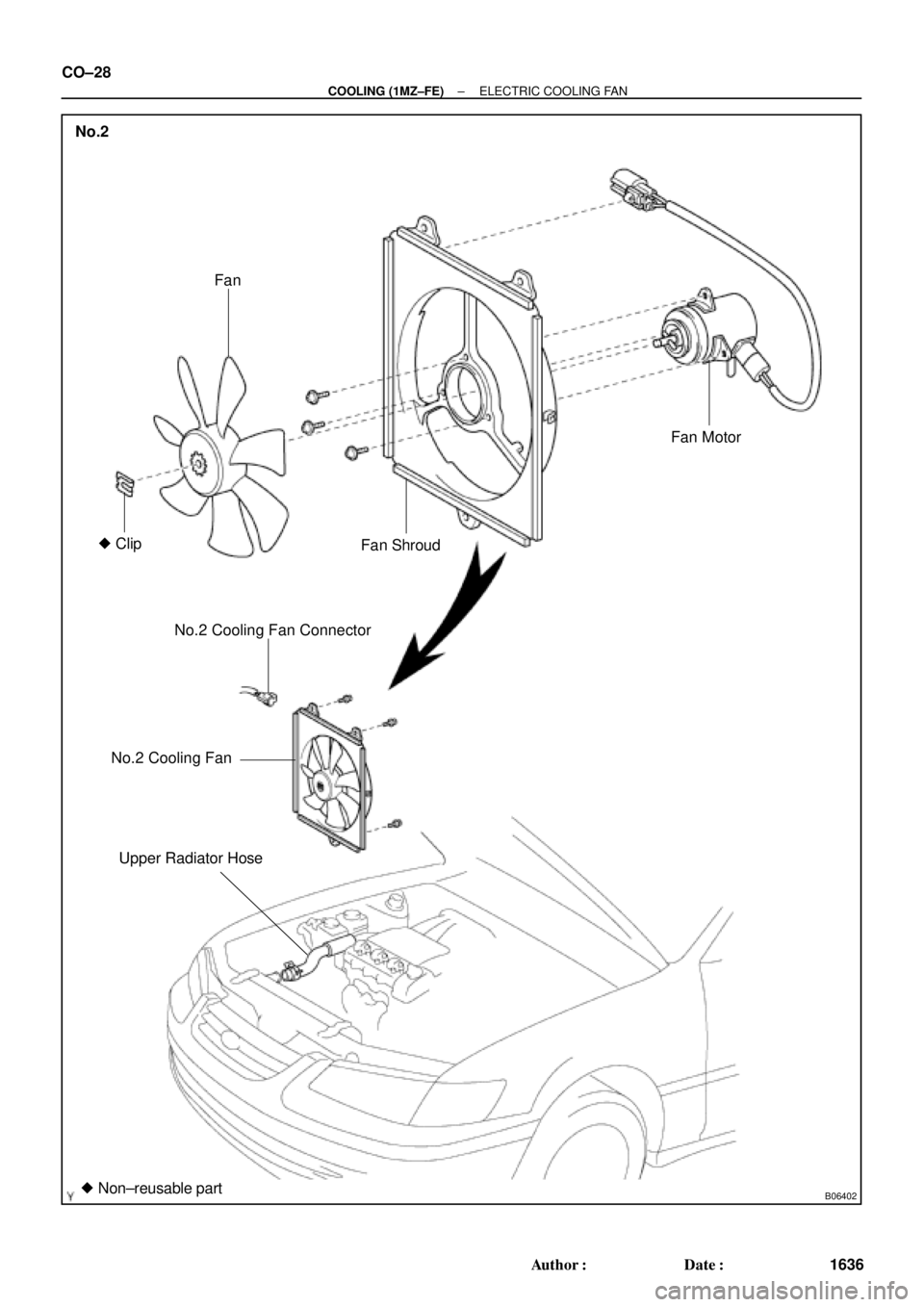
No.2
Fan
� Clip
Fan ShroudFan Motor
No.2 Cooling Fan Connector
No.2 Cooling Fan
Upper Radiator Hose
� Non±reusable part
CO±28
± COOLING (1MZ±FE)ELECTRIC COOLING FAN
1636 Author�: Date�:
Page 2411 of 4770
CO03U±03
B05943
B05944
± COOLING (1MZ±FE)ELECTRIC COOLING FAN
CO±29
1637 Author�: Date�:
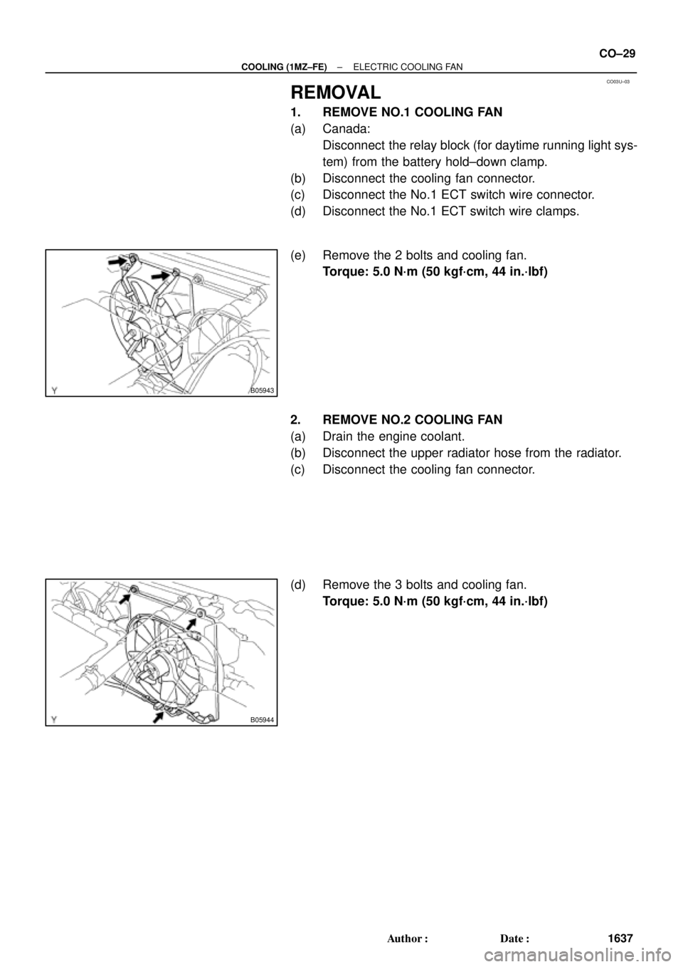
REMOVAL
1. REMOVE NO.1 COOLING FAN
(a) Canada:
Disconnect the relay block (for daytime running light sys-
tem) from the battery hold±down clamp.
(b) Disconnect the cooling fan connector.
(c) Disconnect the No.1 ECT switch wire connector.
(d) Disconnect the No.1 ECT switch wire clamps.
(e) Remove the 2 bolts and cooling fan.
Torque: 5.0 N´m (50 kgf´cm, 44 in.´lbf)
2. REMOVE NO.2 COOLING FAN
(a) Drain the engine coolant.
(b) Disconnect the upper radiator hose from the radiator.
(c) Disconnect the cooling fan connector.
(d) Remove the 3 bolts and cooling fan.
Torque: 5.0 N´m (50 kgf´cm, 44 in.´lbf)
Page 2412 of 4770
CO03V±03
B05945
Protrusion
S04584
S04587
B05946
Protrusion
CO±30
± COOLING (1MZ±FE)ELECTRIC COOLING FAN
1638 Author�: Date�:
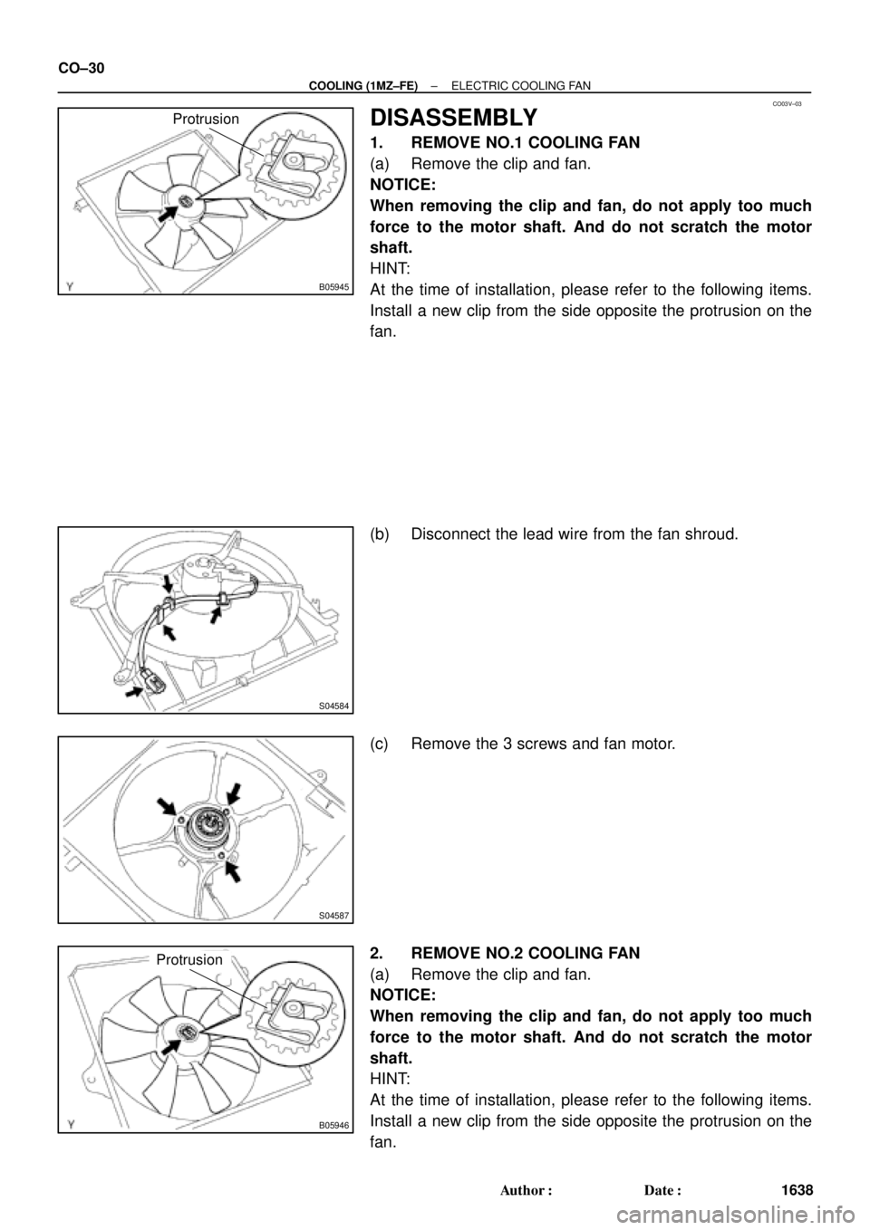
DISASSEMBLY
1. REMOVE NO.1 COOLING FAN
(a) Remove the clip and fan.
NOTICE:
When removing the clip and fan, do not apply too much
force to the motor shaft. And do not scratch the motor
shaft.
HINT:
At the time of installation, please refer to the following items.
Install a new clip from the side opposite the protrusion on the
fan.
(b) Disconnect the lead wire from the fan shroud.
(c) Remove the 3 screws and fan motor.
2. REMOVE NO.2 COOLING FAN
(a) Remove the clip and fan.
NOTICE:
When removing the clip and fan, do not apply too much
force to the motor shaft. And do not scratch the motor
shaft.
HINT:
At the time of installation, please refer to the following items.
Install a new clip from the side opposite the protrusion on the
fan.