Page 3727 of 4770

± LUBRICATION (5S±FE)OIL PUMP
LU±13
1659 Author�: Date�:
INSTALLATION
1. INSTALL OIL PUMP
Install")
LU03P±03
Z19249
A
BB AA A AA A
A A
A
S05928
LU0420
Seal Width
3 ± 5 mm
A
A
BBC
C
5 mm (0.20 in.)
± LUBRICATION (5S±FE)OIL PUMP
LU±13
1659 Author�: Date�:
INSTALLATION
1. INSTALL OIL PUMP
Install a new gasket and the oil pump with the 12 bolts. Uniformi-
ty tighten the bolts in several passes.
Torque: 8.8 N´m (90 kgf´cm, 78 in.´lbf)
HINT:
Each bolt length is indicated in the illustration.
Bolt length:
25 mm (0.98 in.) for A
35 mm (1.38 in.) for B
2. INSTALL OIL PUMP PULLEY (See page EM±23)
3. INSTALL CRANKSHAFT TIMING PULLEY
(See page EM±23)
4. INSTALL NO.2 IDLER PULLEY (See page EM±23)
5. INSTALL TIMING BELT (See page EM±23)
6. INSTALL OIL STRAINER
Install a new gasket and the oil strainer with the bolt and 2 nuts.
Torque: 5.4 N´m (55 kgf´cm, 48 in.´lbf)
7. INSTALL OIL PAN
(a) Remove any old seal packing (FIPG) material and be
careful not to drop any oil on the contact surfaces of the
oil pan and cylinder block.
�Using a razor blade and gasket scraper, remove all
the old packing (FIPG) material from the gasket sur-
faces and sealing groove.
�Thoroughly clean all components to remove all the
loose material.
�Using a non±residue solvent, clean both sealing
surface.
NOTICE:
Do not use a solvent which will affect the painted surfaces.
(b) Apply seal packing to the oil pan shown in the illustration.
Seal packing: Part No. 08826±00080 or equivalent
�Install a nozzle that has been cut to a 3 ± 5 mm (0.12
± 0.20 in.) opening.
�Parts must be assembled within 5 minutes of ap-
plication. Otherwise the material must be removed
and reapplied.
Page 3728 of 4770
LU±14
± LUBRICATION (5S±FE)OIL PUMP
1660 Author�: Date�: �
Immediately remove nozzle from the tube and rein-
stall the cap.
(c) Install the oil pan with the 17 bolts and 2 nuts. Uniformly
tighten the bolts and nuts in several passes.
(d) Install the dipstick.
8. INSTALL NO.2 REAR END PLATE, OIL PAN INSULA-
TOR AND EXHAUST PIPE BRACKET
(See page EM±75)
9. INSTALL LH STIFFENER PLATE AND NO.2 EXHAUST
MANIFOLD STAY (See page EM±23)
10. INSTALL FRONT EXHAUST PIPE
(See page EM±75)
11. FILL WITH ENGINE OIL
12. START ENGINE AND CHECK FOR OIL LEAKS
13. RECHECK ENGINE OIL LEVEL
Page 3739 of 4770
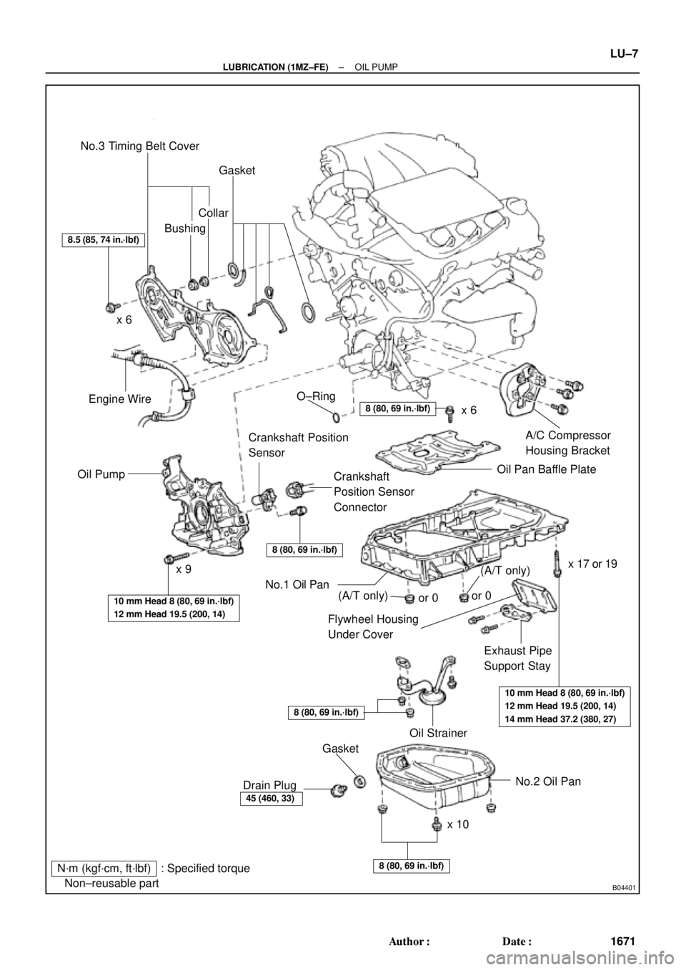
B04401
N´m (kgf´cm, ft´lbf) : Specified torque
� Non±reusable partNo.3 Timing Belt Cover
Gasket
BushingCollar
A/C Compressor
Housing Bracket
Oil Pan Baffle Plate
Crankshaft
Position Sensor
Connector Crankshaft Position
Sensor
Oil PumpEngine Wire
Flywheel Housing
Under Cover
Exhaust Pipe
Support Stay
Oil Strainer
No.2 Oil Pan
x 10x 6
x 9� O±Ring
No.1 Oil Pan
� Gasket
Drain Plug
8.5 (85, 74 in.´lbf)
8 (80, 69 in.´lbf)
8 (80, 69 in.´lbf)
10 mm Head 8 (80, 69 in.´lbf)
12 mm Head 19.5 (200, 14)
10 mm Head 8 (80, 69 in.´lbf)
12 mm Head 19.5 (200, 14)
14 mm Head 37.2 (380, 27)
8 (80, 69 in.´lbf)
45 (460, 33)
8 (80, 69 in.´lbf)
x 6
x 17 or 19
(A/T only)(A/T only)or 0or 0
± LUBRICATION (1MZ±FE)OIL PUMP
LU±7
1671 Author�: Date�:
Page 3741 of 4770
LU028±03
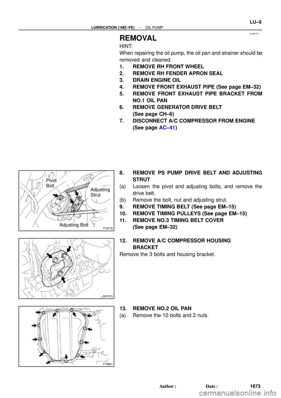
P18778Adjusting Bolt
Adjusting
Strut Pivot
Bolt
B01015
P18801
± LUBRICATION (1MZ±FE)OIL PUMP
LU±9
1673 Author�: Date�:
REMOVAL
HINT:
When repairing the oil pump, the oil pan and strainer should be
removed and cleaned.
1. REMOVE RH FRONT WHEEL
2. REMOVE RH FENDER APRON SEAL
3. DRAIN ENGINE OIL
4. REMOVE FRONT EXHAUST PIPE (See page EM±32)
5. REMOVE FRONT EXHAUST PIPE BRACKET FROM
NO.1 OIL PAN
6. REMOVE GENERATOR DRIVE BELT
(See page CH±6)
7. DISCONNECT A/C COMPRESSOR FROM ENGINE
(See page AC±41)
8. REMOVE PS PUMP DRIVE BELT AND ADJUSTING
STRUT
(a) Loosen the pivot and adjusting bolts, and remove the
drive belt.
(b) Remove the bolt, nut and adjusting strut.
9. REMOVE TIMING BELT (See page EM±15)
10. REMOVE TIMING PULLEYS (See page EM±15)
11. REMOVE NO.3 TIMING BELT COVER
(See page EM±32)
12. REMOVE A/C COMPRESSOR HOUSING
BRACKET
Remove the 3 bolts and housing bracket.
13. REMOVE NO.2 OIL PAN
(a) Remove the 10 bolts and 2 nuts.
Page 3742 of 4770
OIL PUMP
1674 Author�: Date�:
(b) Insert the blade of SST between the No.1 and No.2 oil
pans, and cut off applied sealer an")
P12716
SST
SST
P18802
B04136
B04137
P20050Pry LU±10
± LUBRICATION (1MZ±FE)OIL PUMP
1674 Author�: Date�:
(b) Insert the blade of SST between the No.1 and No.2 oil
pans, and cut off applied sealer and remove the No.1 oil
pan.
SST 09032±00100
NOTICE:
�Be careful not to the damage the No.2 oil pan contact
surface of the No.1 oil pan.
�Be careful not to damage the No.2 oil pan flange.
14. REMOVE OIL STRAINER
Remove the bolt, 2 nuts, oil strainer and gasket.
15. REMOVE NO.1 OIL PAN
(a) Remove the 2 bolts, exhaust pipe support stay and fly-
wheel housing under cover.
(b) Remove the 19 bolts (or 17 bolts and 2 nuts).
(c) Using a screwdriver, remove the oil pan by prying the por-
tions between the cylinder block and oil pan.
NOTICE:
Be careful not to damage the contact surfaces of the cylin-
der block and oil pan.
16. REMOVE BAFFLE PLATE FROM NO.1 OIL PAN
17. REMOVE CRANKSHAFT POSITION SENSOR
18. REMOVE OIL PUMP
(a) Remove the 9 bolts.
(b) Remove the oil pump by prying a screwdriver between the
oil pump and main bearing cap.
(c) Remove the O±ring.
Page 3748 of 4770
P12694
LU±16
± LUBRICATION (1MZ±FE)OIL PUMP
1680 Author�: Date�:
(d) Engage the spline teeth of the oil pump drive gear with the
large teeth of the crankshaft, and slide the oil pump on the
crankshaft.
(e) Install the oil pump with the 9 bolts. Uniformly tighten the
bolts in several passes.
Torque:
10 mm head: 8 N´m (80 kgf´cm, 69 in.´lbf)
12 mm head: 19.5 N´m (200 kgf´cm, 14 ft´lbf)
2. INSTALL CRANKSHAFT POSITION SENSOR
3. INSTALL BAFFLE PLATE TO NO.1 OIL PAN
Torque: 8 N´m (80 kgf´cm, 69 in.´lbf)
4. INSTALL NO.1 OIL PAN
(a) Remove any old packing (FIPG) material and be careful
not to drop any oil on the contact surfaces of the oil pan,
oil pump and cylinder block.
�Using a razor blade and gasket scraper, remove all
the old packing (FIPG) material from the gasket sur-
faces and sealing grooves.
�Thoroughly clean all components to remove all the
loose material.
�Using a non±residue solvent, clean both sealing
surfaces.
Page 3749 of 4770
OIL PUMP
LU±17
1681 Author�: Date�:
(b) Appl")
B04402
A Region ºXºRegion ºYº
A
CB B
C
Seal Width
Type A: 4 ± 5 mm
Type B: 3 ± 4 mmRegion ºXºRegion ºYº
AC Type A
Type B
± LUBRICATION (1MZ±FE)OIL PUMP
LU±17
1681 Author�: Date�:
(b) Apply seal packing to the oil pan as shown in the illustra-
tion.
Seal packing: Part No. 08826±00080 or equivalent
Region ºXº is at the outer side of the bolt hole.
Region ºYº is at the inner side of the bolt hole.
�Install a nozzle that has been cut to a 4 ± 5 mm (0.16
± 0.20 in.) (Type A) or 3 ± 4 mm (0.12 ± 0.16 in.)
(Type B) opening.
HINT:
Avoid applying an excessive amount to the surface.
�Parts must be assembled within 3 minutes of ap-
plication. Otherwise the material must be removed
and reapplied.
�Immediately remove nozzle from the tube and rein-
stall cap.
(c) Install the oil pan with the 19 bolts (or 17 bolts and 2 nuts).
Uniformly tighten the bolts and nuts in several passes.
Torque:
10 mm head: 8 N´m (80 kgf´cm, 69 in.´lbf)
12 mm head: 19.5 N´m (200 kgf´cm, 14 ft´lbf)
14 mm head: 37.2 N´m (380 kgf´cm, 27 ft´lbf)
(d) Install the flywheel housing under cover and exhaust pipe
support stay with the 2 bolts.
Torque: 7.8 N´m (80 kgf´cm, 69 in.´lbf)
5. INSTALL OIL STRAINER
Install a new gasket and the oil strainer with the bolt and 2 nuts.
Torque: 8 N´m (80 kgf´cm, 69 in.´lbf)
6. INSTALL NO.2 OIL PAN
(a) Remove any old packing (FIPG) material and be careful
not to drop any oil on the contact surface of the No.1 and
No.2 oil pans.
�Using a razor blade and gasket scraper, remove all
the old packing (FIPG) material from the gasket sur-
faces and sealing grooves.
�Thoroughly clean all components to remove all the
loose material.
�Using a non±residue solvent, clean both sealing
surfaces.
NOTICE:
Do not use a solvent which will affect the painted surfaces.
Page 3750 of 4770
OIL PUMP
1682 Author�: Date�:
(b) Apply seal packing to the No.2 oil pan as shown in the il-
lustration.
Seal packing:
Part No. 08826�")
P12568
A
A
BB
Seal Width
4 ± 5 mm LU±18
± LUBRICATION (1MZ±FE)OIL PUMP
1682 Author�: Date�:
(b) Apply seal packing to the No.2 oil pan as shown in the il-
lustration.
Seal packing:
Part No. 08826±00080 or equivalent
�Install a nozzle that has been cut to a 4 ± 5 mm (0.16
± 0.20 in.) opening.
HINT:
Avoid applying an excessive amount to the surface.
�Parts must be assembled within 3 minutes of ap-
plication. Otherwise the material must be removed
and reapplied.
�Immediately remove nozzle from the tube and rein-
stall cap.
(c) Install the No.2 oil pan with the 10 bolts and 2 nuts. Uni-
formly tighten the bolts and nuts in several passes.
Torque: 8 N´m (80 kgf´cm, 69 in.´lbf)
7. INSTALL A/C COMPRESSOR HOUSING BRACKET
Torque: 25 N´m (250 kgf´cm, 18 ft´lbf)
8. INSTALL NO.3 TIMING BELT COVER
(See page EM±21)
9. INSTALL TIMING PULLEYS (See page EM±21)
10. INSTALL TIMING BELT (See page EM±21)
11. INSTALL ADJUSTING STRUT AND PS PUMP DRIVE
BELT
(a) Temporarily install the adjusting strut with the bolt and the
nut.
(b) Install the drive belt with the pivot and adjusting bolts.
Torque: 43.1 N´m (440 kgf´cm, 32 ft´lbf)
(c) Tighten the nut.
Torque: 43.1 N´m (440 kgf´cm, 32 ft´lbf)
12. INSTALL A/C COMPRESSOR (See page AC±47)
13. INSTALL GENERATOR DRIVE BELT
(See page CH±16)
14. INSTALL FRONT EXHAUST PIPE BRACKET TO
NO.1 OIL PAN
Torque: 21 N´m (210 kgf´cm, 15 ft´lbf)
15. INSTALL FRONT EXHAUST PIPE (See page EM±76)
16. REMOVE RH FENDER APRON SEAL
17. REMOVE RH FRONT WHEEL
18. FILL ENGINE WITH OIL
19. START ENGINE AND CHECK FOR LEAKS
20. RECHECK ENGINE OIL LEVEL