Page 3588 of 4770
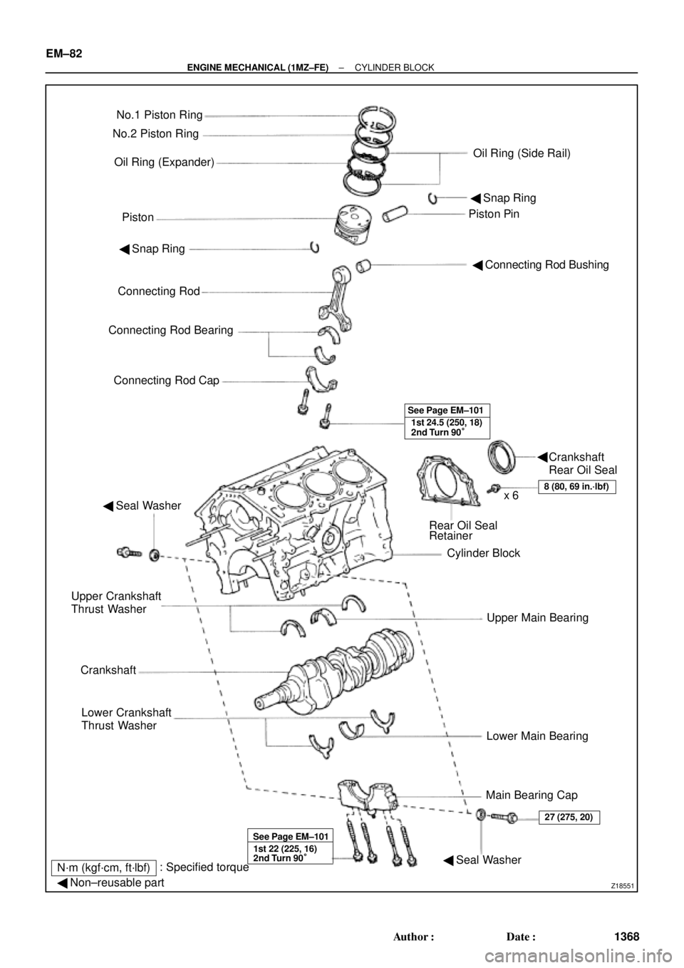
Z18551
No.1 Piston Ring
Oil Ring (Expander)
PistonPiston Pin No.2 Piston Ring
Oil Ring (Side Rail)
� Snap Ring
� Connecting Rod Bushing � Snap Ring
Connecting Rod
Connecting Rod Bearing
Connecting Rod Cap
1st 24.5 (250, 18)
2nd Turn 90° See Page EM±101
� Seal Washer
Rear Oil Seal
Retainer
Cylinder Block
Upper Main Bearing
Lower Main Bearing
Main Bearing Cap Upper Crankshaft
Thrust Washer
Crankshaft
Lower Crankshaft
Thrust Washer
8 (80, 69 in.´lbf)x 6
1st 22 (225, 16)
2nd Turn 90° See Page EM±101
� Seal Washer
27 (275, 20)
N´m (kgf´cm, ft´lbf): Specified torque
� Non±reusable part
Crankshaft
Rear Oil Seal � EM±82
± ENGINE MECHANICAL (1MZ±FE)CYLINDER BLOCK
1368 Author�: Date�:
Page 3590 of 4770
CYLINDER BLOCK
1370 Author�: Date�:
11. REMOVE WATER I")
P18762
P18763
WaterSeal
Plate
Oil Filter
Union
12 mm
Hexagon
Wrench
Coolant
Drain
Union
P12410
P12508
P12695
EM±84
± ENGINE MECHANICAL (1MZ±FE)CYLINDER BLOCK
1370 Author�: Date�:
11. REMOVE WATER INLET HOUSING
(a) Remove the engine wire band.
(b) Disconnect the engine wire clamp from the bracket.
(c) Remove the 8 bolts, 2 nuts and water inlet housing.
12. REMOVE WATER PUMP (See page CO±6)
13. REMOVE NO.2 OIL PAN (See page LU±9)
14. REMOVE OIL STRAINER (See page LU±9)
15. REMOVE NO.1 OIL PAN (See page LU±9)
16. REMOVE OIL PUMP (See page LU±9)
17. REMOVE OIL FILTER (See page LU±9)
18. REMOVE OIL FILTER UNION
Using a 12 mm hexagon wrench, remove the oil filter union.
19. REMOVE WATER SEAL PLATE
Remove the 2 nuts and seal plate.
20. REMOVE ENGINE COOLANT DRAIN UNION
21. REMOVE EGR COOLER
Remove the 3 bolts, 2 nuts, EGR cooler and gasket.
22. REMOVE REAR OIL SEAL RETAINER
(a) Remove the 6 bolts.
(b) Using a screwdriver, remove the oil seal retainer by prying
the portions between the oil seal retainer and main bear-
ing cap.
23. CHECK CONNECTING ROD THRUST CLEARANCE
Using a dial indicator, measure the thrust clearance while mov-
ing the connecting rod back and forth.
Standard thrust clearance:
0.15 ± 0.30 mm (0.0059 ± 0.0118 in.)
Maximum thrust clearance: 0.35 mm (0.0138 in.)
If the thrust clearance is greater than maximum, replace the
connecting rod assembly(s). If necessary, replace the crank-
shaft.
Page 3598 of 4770
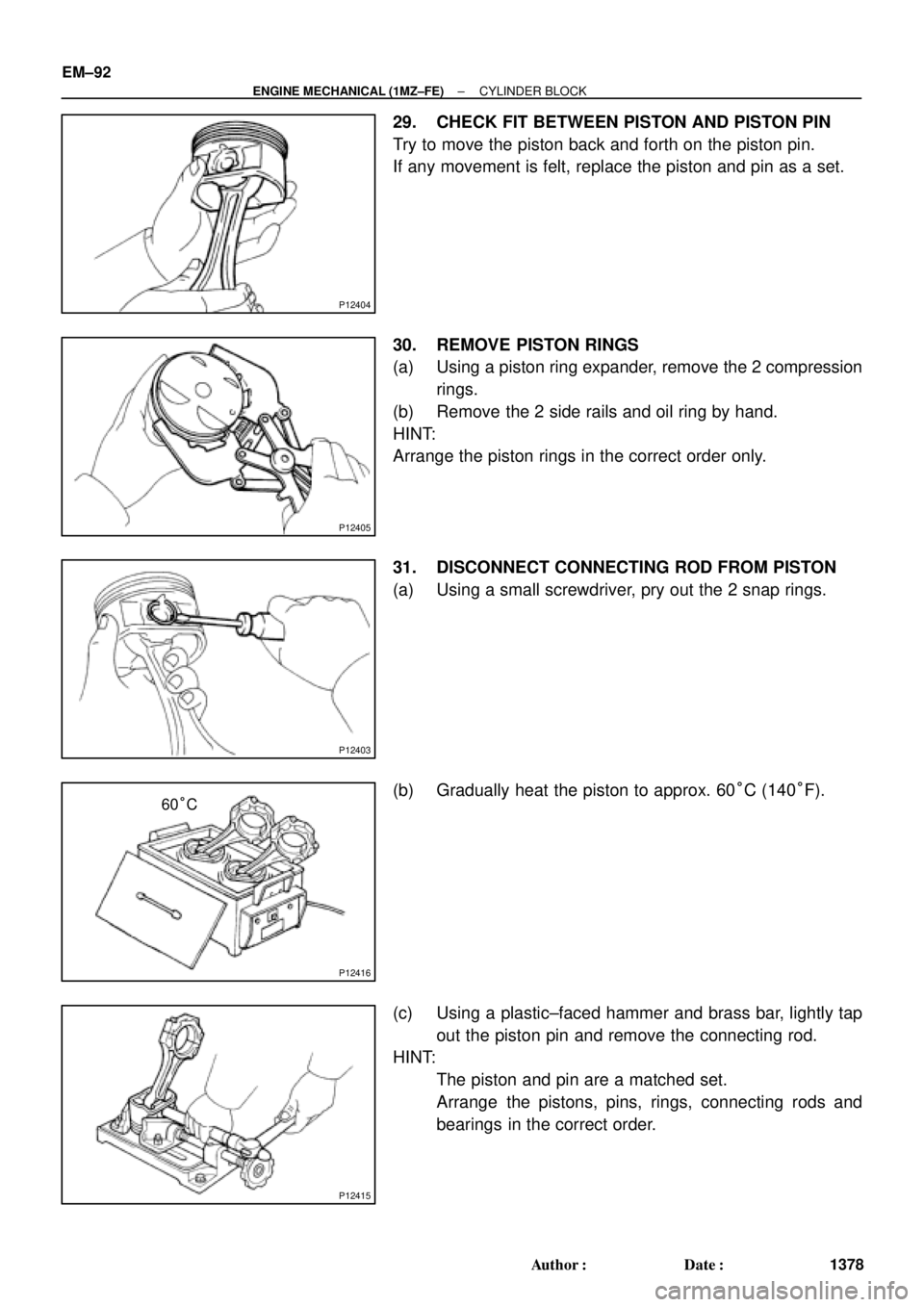
P12404
P12405
P12403
P12416
60°C
P12415
EM±92
± ENGINE MECHANICAL (1MZ±FE)CYLINDER BLOCK
1378 Author�: Date�:
29. CHECK FIT BETWEEN PISTON AND PISTON PIN
Try to move the piston back and forth on the piston pin.
If any movement is felt, replace the piston and pin as a set.
30. REMOVE PISTON RINGS
(a) Using a piston ring expander, remove the 2 compression
rings.
(b) Remove the 2 side rails and oil ring by hand.
HINT:
Arrange the piston rings in the correct order only.
31. DISCONNECT CONNECTING ROD FROM PISTON
(a) Using a small screwdriver, pry out the 2 snap rings.
(b) Gradually heat the piston to approx. 60°C (140°F).
(c) Using a plastic±faced hammer and brass bar, lightly tap
out the piston pin and remove the connecting rod.
HINT:
�The piston and pin are a matched set.
�Arrange the pistons, pins, rings, connecting rods and
bearings in the correct order.
Page 3608 of 4770
S06043
Front Mark MAHLE Made
RH Piston
LH Piston(1 Cavity)
Front Mark
(Mold Mark)
Front Mark
(1 Cavity)
Front Mark
(Mold Mark)
Z09179
Code Mark
Code Mark No.1
No.2
S06058
RH Piston
Lower Side Rail
No.2
Compression
Front Mark
Expander
Upper Side Rail
No.1
Compression
Lower Side Rail
Upper Side RailFront Mark LH PistonNo.2
Compression
Expander
No.1
CompressionFront Markor EM±102
± ENGINE MECHANICAL (1MZ±FE)CYLINDER BLOCK
1388 Author�: Date�:
2. INSTALL PISTON RINGS
(a) Install the oil ring expander and 2 side rails by hand.
(b) Using a piston ring expander, install the 2 compression
rings with the code mark facing upward.
Code mark:
No.11R, T or G1
No.22R, 2T or G2
(c) Position the piston rings so that the ring ends are as
shown.
NOTICE:
Do not align the ring ends.
Page 3614 of 4770
CYLINDER BLOCK
1394 Author�: Date�:
17. INSTALL ENGINE COOLANT DRAIN UNION
(a) Apply seal packing to 2 or 3")
P12477
Seal Packing
Z09223
Seal Width
3 ± 5 mmA
BA
B EM±108
± ENGINE MECHANICAL (1MZ±FE)CYLINDER BLOCK
1394 Author�: Date�:
17. INSTALL ENGINE COOLANT DRAIN UNION
(a) Apply seal packing to 2 or 3 threads.
Seal packing: Part No. 08826±00100 or equivalent
(b) Install the drain union.
Torque: 39 N´m (400 kgf´cm, 29 ft´lbf)
HINT:
After applying the specified torque, rotate the drain union clock-
wise until its drain port is facing downward.
18. INSTALL WATER SEAL PLATE
(a) Remove any old packing (FIPG) material and be careful
not to drop any oil on the contact surfaces of the seal plate
and cylinder block.
�Using a razor blade and gasket scraper, remove all
the old packing (FIPG) material from the gasket sur-
faces and sealing groove.
�Thoroughly clean all components to remove all the
loose material.
�Using a non±residue solvent, clean both sealing
surfaces.
(b) Apply seal packing to the seal plate as shown in the il-
lustration.
Seal packing: Part No. 08826±00100 or equivalent
�Install a nozzle that has been cut to a 3 ± 5 mm (0.12
± 0.20 in.) opening.
�Parts must be assembled within 3 minutes of ap-
plication. Otherwise the material must be removed
and reapplied.
�Immediately remove nozzle from the tube and rein-
stall cap.
(c) Install the seal plate with the 2 nuts.
Torque: 18 N´m (180 kgf´cm, 13 ft´lbf)
19. INSTALL OIL FILTER UNION
Torque: 30 N´m (310 kgf´cm, 22 ft´lbf)
20. INSTALL OIL FILTER (See page LU±15)
21. INSTALL OIL PUMP (See page LU±15)
22. INSTALL NO.1 OIL PAN (See page LU±15)
23. INSTALL OIL STRAINER (See page LU±15)
24. INSTALL NO.2 OIL PAN (See page LU±15)
25. INSTALL WATER PUMP (See page CO±8)
26. INSTALL WATER INLET HOUSING
(a) Remove any old packing (FIPG) material and be careful
not to drop any oil on the contact surfaces of the water in-
let housing and cylinder block.
�Using a razor blade and gasket scraper, remove all
the old packing (FIPG) material from the gasket sur-
faces and sealing grooves.
�Thoroughly clean all components to remove all the
loose material.
Page 3718 of 4770
LU03J±03
S05595
Engine Moving Control Rod
No.2 RH Engine Mounting Bracket
Generator Drive Belt
RH Front Fender Apron Seal
PS Pump Drive Belt
Exhaust Pipe Bracket
Oil Pan InsulatorGround Strap Connector
No.2 Rear End Plate
No.2 Exhaust
Manifold Stay
(TMMK Made)
(TMC Made)LH Stiffener Plate
� Gasket
Bracket
Front Exhaust Pipe
StayBracket� Gasket
N´m (kgf´cm, ft´lbf): Specified torque
� Non±reusable part
64 (650, 47)
52 (530, 38)
62 (630, 46)56 (570, 41) 64 (650, 47)
��
� LU±4
± LUBRICATION (5S±FE)OIL PUMP
1650 Author�: Date�:
OIL PUMP
COMPONENTS
Page 3719 of 4770
B06345
No.2 Timing Belt Cover
No.1 Timing Belt Cover* Gasket
Wire
ClampGeneratorGenerator Wire
Generator Connector
Crankshaft Pulley
No.2 Idler Pulley
Oil Pump Pulley
Crankshaft
Timing Pulley
Crankshaft Position SensorTiming Belt Guide
Wire ClampWire
Clamp
Timing Belt
Clamp
No.1 Idler Pulley
Tension Spring � GasketClamp
� Gasket
� GasketHigh±Tension Cord
Spark Plug
Oil Strainer
Drain Plug
N´m (kgf´cm, ft´lbf): Specified torque
� Non±reusable partx 17
* Gasket
* Replace only if damagedOil Pump
x 10
8.8 (90, 78 in.´lbf)5.4 (55, 48 in.´lbf)
5.4 (55, 48 in.´lbf)
24 (245, 18)
42 (425, 31)
108 (1,100, 80)
18 (180, 13)
42 (425, 31)
Oil Pan
± LUBRICATION (5S±FE)OIL PUMP
LU±5
1651 Author�: Date�:
Page 3721 of 4770
OIL PUMP
LU±7
1653 Author�: Date�:
REMOVAL
HINT:
When repairing the oil pump, the oil pan and strainer should be
removed and cleaned.
1.")
LU03K±03
S05311
S05952
SST
SST
S05928
± LUBRICATION (5S±FE)OIL PUMP
LU±7
1653 Author�: Date�:
REMOVAL
HINT:
When repairing the oil pump, the oil pan and strainer should be
removed and cleaned.
1. DRAIN ENGINE OIL
2. REMOVE FRONT EXHAUST PIPE (See page EM±69)
3. REMOVE NO.2 EXHAUST MANIFOLD STAY AND LH
STIFFENER PLATE (See page EM±69)
4. REMOVE EXHAUST PIPE BRACKET, OIL PAN INSU-
LATOR AND NO.2 REAR END PLATE
(See page EM±69)
5. REMOVE OIL PAN
(a) Remove the oil dipstick.
(b) Remove the 17 bolts and 2 nuts.
(c) Insert the blade of SST between the cylinder block and oil
pan, and cut off applied sealer and remove the oil pan.
SST 09032±00100
NOTICE:
�Do not use SST for the oil pump body side and rear oil
seal retainer.
�Be careful not to damage the oil pan flange.
6. REMOVE OIL STRAINER
Remove the bolt, 2 nuts, oil strainer and gasket.
7. REMOVE TIMING BELT (See page EM±17)
8. REMOVE NO.2 IDLER PULLEY
Remove the bolt and idler pulley.
9. REMOVE CRANKSHAFT TIMING PULLEY
(See page EM±17)
10. REMOVE OIL PUMP PULLEY (See page EM±17)

Front Mark
(Mold Mark)
Front Mark
(1 Cavity)
Front Mark
(Mold Mark)
Z09179
Code Mark
Code Mark No.1
No.2
S06058
RH Piston
Lower Side Rail
No.")

