Page 3403 of 4770
EM082±04
Z19417
TDCCrankshaft
Gear
No.1 Balance
Shaft Gear30°
AB
AB 1
2
3
4
100°
210°
280°
P06121
C C
Z19411
No.1 Balance ShaftMark B
Mark A
No.2 Housing
Z19413
No.1 Balance
Shaft
Mark B
Mark A No.2 Housing
± ENGINE MECHANICAL (5S±FE)BALANCE SHAFT BACKLASH
EM±11
1183 Author�: Date�:
BALANCE SHAFT BACKLASH
ON±VEHICLE INSPECTION
1. REMOVE OIL PAN AND OIL STRAINER
(See page LU±7)
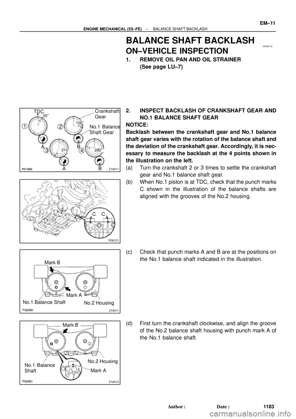
2. INSPECT BACKLASH OF CRANKSHAFT GEAR AND
NO.1 BALANCE SHAFT GEAR
NOTICE:
Backlash between the crankshaft gear and No.1 balance
shaft gear varies with the rotation of the balance shaft and
the deviation of the crankshaft gear. Accordingly, it is nec-
essary to measure the backlash at the 4 points shown in
the illustration on the left.
(a) Turn the crankshaft 2 or 3 times to settle the crankshaft
gear and No.1 balance shaft gear.
(b) When No.1 piston is at TDC, check that the punch marks
C shown in the illustration of the balance shafts are
aligned with the grooves of the No.2 housing.
(c) Check that punch marks A and B are at the positions on
the No.1 balance shaft indicated in the illustration.
(d) First turn the crankshaft clockwise, and align the groove
of the No.2 balance shaft housing with punch mark A of
the No.1 balance shaft.
Page 3405 of 4770
Z19415
No.1 Balance
Shaft
Mark B
Mark A
No.2 Housing
Z19408
2
46 153
Z19409
1
35 Pull
264
± ENGINE MECHANICAL (5S±FE)BALANCE SHAFT BACKLASH
EM±13
1185 Author�: Date�:
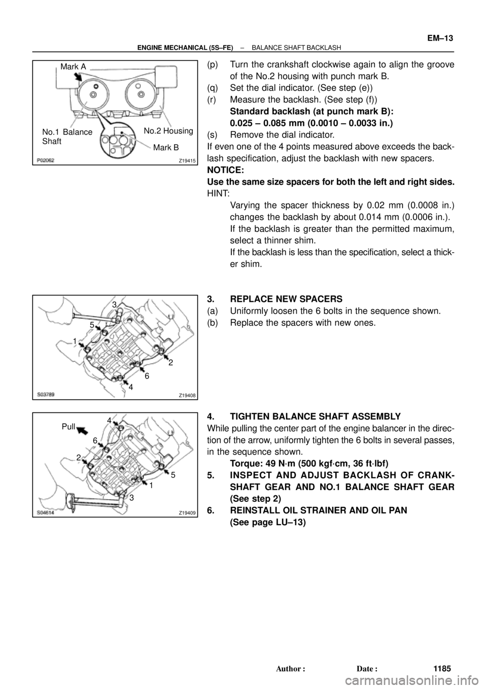
(p) Turn the crankshaft clockwise again to align the groove
of the No.2 housing with punch mark B.
(q) Set the dial indicator. (See step (e))
(r) Measure the backlash. (See step (f))
Standard backlash (at punch mark B):
0.025 ± 0.085 mm (0.0010 ± 0.0033 in.)
(s) Remove the dial indicator.
If even one of the 4 points measured above exceeds the back-
lash specification, adjust the backlash with new spacers.
NOTICE:
Use the same size spacers for both the left and right sides.
HINT:
�Varying the spacer thickness by 0.02 mm (0.0008 in.)
changes the backlash by about 0.014 mm (0.0006 in.).
�If the backlash is greater than the permitted maximum,
select a thinner shim.
�If the backlash is less than the specification, select a thick-
er shim.
3. REPLACE NEW SPACERS
(a) Uniformly loosen the 6 bolts in the sequence shown.
(b) Replace the spacers with new ones.
4. TIGHTEN BALANCE SHAFT ASSEMBLY
While pulling the center part of the engine balancer in the direc-
tion of the arrow, uniformly tighten the 6 bolts in several passes,
in the sequence shown.
Torque: 49 N´m (500 kgf´cm, 36 ft´lbf)
5. INSPECT AND ADJUST BACKLASH OF CRANK-
SHAFT GEAR AND NO.1 BALANCE SHAFT GEAR
(See step 2)
6. REINSTALL OIL STRAINER AND OIL PAN
(See page LU±13)
Page 3459 of 4770
S05316
M/T
Engine
No.2 Exhaust
Manifold Stay
(TMMK Made)
(TMC Made)
Exhaust Pipe Bracket
Oil Pan
Insulator
No.1 Exhaust
Manifold Stay
Back±Up Light Switch ConnectorNo.2 Rear End Plate Flywheel
LH Stiffener Plate
Clutch Disk
Clutch Cover
Engine Wire
VSS Connector
Wire Clamp
Ground Strap
Transaxle No.1 Rear End PlateIntake Manifold
Stay RH Stiffener Plate
N´m (kgf´cm, ft´lbf)
� Precoated partx 8
88 (900, 65)
19 (195, 14)
64(650, 47)
64(650, 47)
64(650, 47)64(650, 47)
�
: Specified torquex 6
± ENGINE MECHANICAL (5S±FE)ENGINE UNIT
EM±67
1239 Author�: Date�:
Page 3460 of 4770
A02187
A/T
Engine
No.2 Exhaust
Manifold Stay
(TMC Made)
Exhaust Pipe Bracket
Oil Pan
InsulatorLH Stiffener Plate
Engine Wire
VSS Connector
Wire Clamp
Ground Strap No.1 Rear End PlateIntake Manifold
Stay RH Stiffener Plate
N´m (kgf´cm, ft´lbf)
� Precoated partx 8 (TMMK Made)
No.2 Rear End Plate
Transaxle No.1 Exhaust
Manifold Stay
PNP Switch
Connector
StarterThrottle Cable Clamp
Solenoid Connector
Front SpacerDrive Plate
Rear Spacer
Throttle Cable
Solenoid Connector x 6
83 (850, 61)27 (280, 20)
66 (670, 48)
66 (670, 20)
66 (670, 48)
66 (670, 48)
� �
: Specified torque
EM±68
± ENGINE MECHANICAL (5S±FE)ENGINE UNIT
1240 Author�: Date�:
Page 3465 of 4770
S05526
TMMK
Made
TMC
Made
A02198
S05530
S05529
Turn
± ENGINE MECHANICAL (5S±FE)ENGINE UNIT
EM±73
1245 Author�: Date�:
30. A/T:
REMOVE STARTER (See page ST±5)
31. DISCONNECT CONNECTORS
(a) Disconnect the VSS connector.
(b) M/T:
Disconnect the back±up light switch connector.
(c) A/T:
Disconnect the PNP switch connector.
(d) A/T:
Disconnect the 2 solenoid connectors.
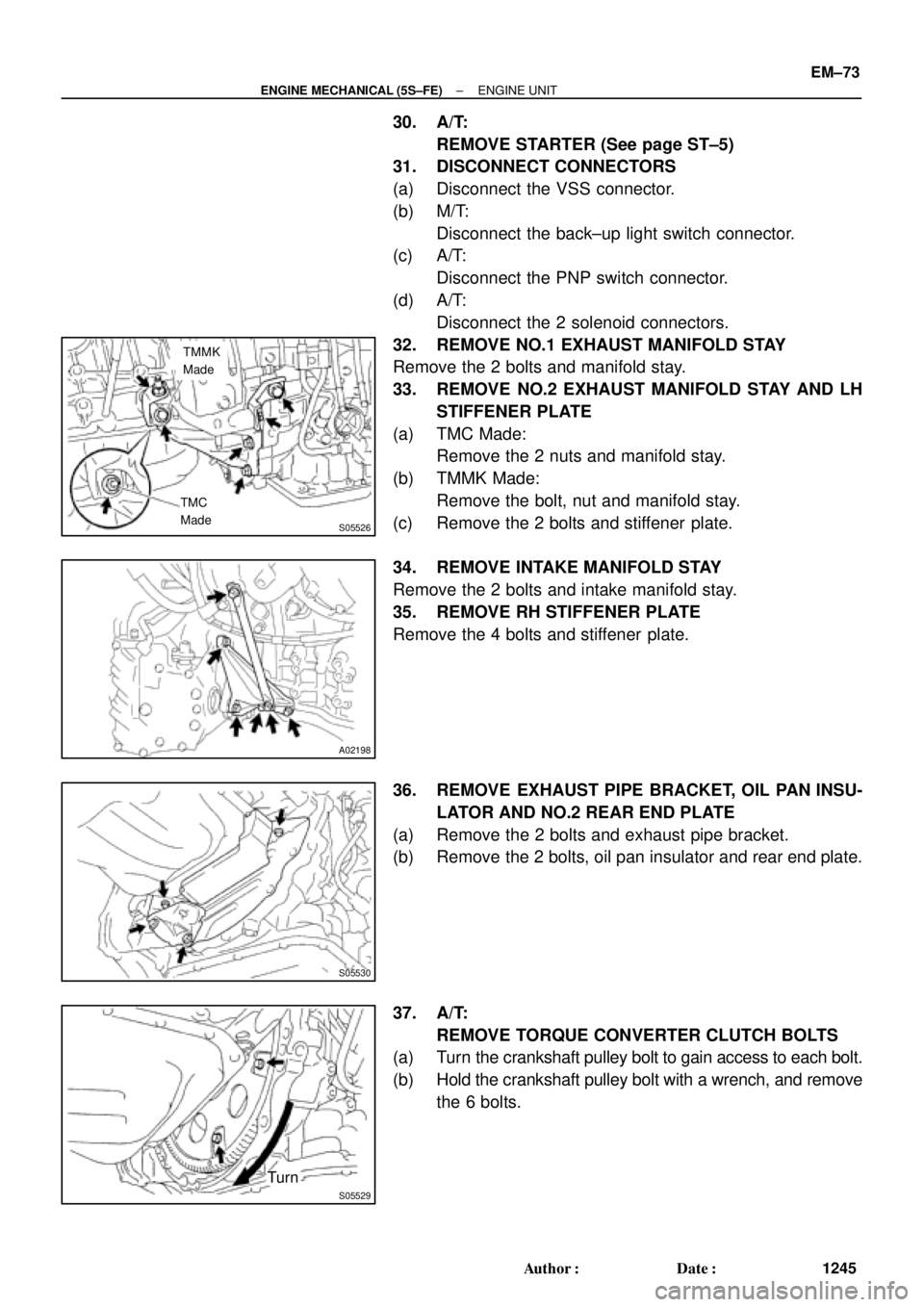
32. REMOVE NO.1 EXHAUST MANIFOLD STAY
Remove the 2 bolts and manifold stay.
33. REMOVE NO.2 EXHAUST MANIFOLD STAY AND LH
STIFFENER PLATE
(a) TMC Made:
Remove the 2 nuts and manifold stay.
(b) TMMK Made:
Remove the bolt, nut and manifold stay.
(c) Remove the 2 bolts and stiffener plate.
34. REMOVE INTAKE MANIFOLD STAY
Remove the 2 bolts and intake manifold stay.
35. REMOVE RH STIFFENER PLATE
Remove the 4 bolts and stiffener plate.
36. REMOVE EXHAUST PIPE BRACKET, OIL PAN INSU-
LATOR AND NO.2 REAR END PLATE
(a) Remove the 2 bolts and exhaust pipe bracket.
(b) Remove the 2 bolts, oil pan insulator and rear end plate.
37. A/T:
REMOVE TORQUE CONVERTER CLUTCH BOLTS
(a) Turn the crankshaft pulley bolt to gain access to each bolt.
(b) Hold the crankshaft pulley bolt with a wrench, and remove
the 6 bolts.
Page 3468 of 4770
Z19014Turn
Black
Colored
Bolt A/T
S05530
A02198
S05526
TMC
Made
TMMK
Made
EM±76
± ENGINE MECHANICAL (5S±FE)ENGINE UNIT
1248 Author�: Date�:
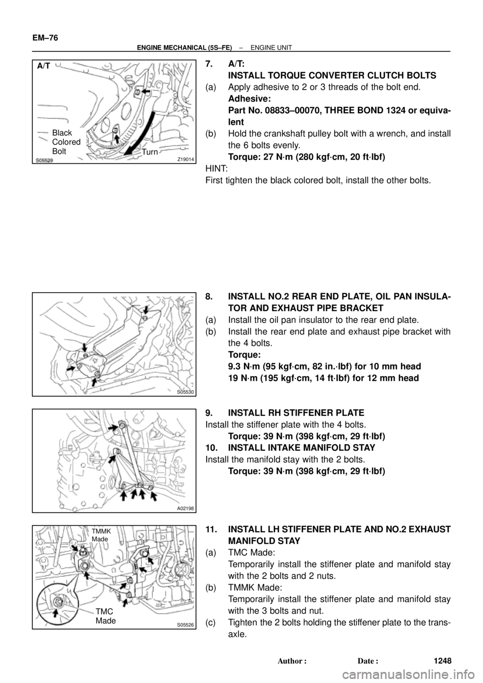
7. A/T:
INSTALL TORQUE CONVERTER CLUTCH BOLTS
(a) Apply adhesive to 2 or 3 threads of the bolt end.
Adhesive:
Part No. 08833±00070, THREE BOND 1324 or equiva-
lent
(b) Hold the crankshaft pulley bolt with a wrench, and install
the 6 bolts evenly.
Torque: 27 N´m (280 kgf´cm, 20 ft´lbf)
HINT:
First tighten the black colored bolt, install the other bolts.
8. INSTALL NO.2 REAR END PLATE, OIL PAN INSULA-
TOR AND EXHAUST PIPE BRACKET
(a) Install the oil pan insulator to the rear end plate.
(b) Install the rear end plate and exhaust pipe bracket with
the 4 bolts.
Torque:
9.3 N´m (95 kgf´cm, 82 in.´lbf) for 10 mm head
19 N´m (195 kgf´cm, 14 ft´lbf) for 12 mm head
9. INSTALL RH STIFFENER PLATE
Install the stiffener plate with the 4 bolts.
Torque: 39 N´m (398 kgf´cm, 29 ft´lbf)
10. INSTALL INTAKE MANIFOLD STAY
Install the manifold stay with the 2 bolts.
Torque: 39 N´m (398 kgf´cm, 29 ft´lbf)
11. INSTALL LH STIFFENER PLATE AND NO.2 EXHAUST
MANIFOLD STAY
(a) TMC Made:
Temporarily install the stiffener plate and manifold stay
with the 2 bolts and 2 nuts.
(b) TMMK Made:
Temporarily install the stiffener plate and manifold stay
with the 3 bolts and nut.
(c) Tighten the 2 bolts holding the stiffener plate to the trans-
axle.
Page 3471 of 4770
S04616
A/T
S05246
S05250
Connector
S05253
± ENGINE MECHANICAL (5S±FE)ENGINE UNIT
EM±79
1251 Author�: Date�:
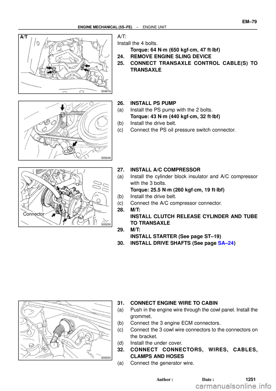
A/T:
Install the 4 bolts.
Torque: 64 N´m (650 kgf´cm, 47 ft´lbf)
24. REMOVE ENGINE SLING DEVICE
25. CONNECT TRANSAXLE CONTROL CABLE(S) TO
TRANSAXLE
26. INSTALL PS PUMP
(a) Install the PS pump with the 2 bolts.
Torque: 43 N´m (440 kgf´cm, 32 ft´lbf)
(b) Install the drive belt.
(c) Connect the PS oil pressure switch connector.
27. INSTALL A/C COMPRESSOR
(a) Install the cylinder block insulator and A/C compressor
with the 3 bolts.
Torque: 25.5 N´m (260 kgf´cm, 19 ft´lbf)
(b) Install the drive belt.
(c) Connect the A/C compressor connector.
28. M/T:
INSTALL CLUTCH RELEASE CYLINDER AND TUBE
TO TRANSAXLE
29. M/T:
INSTALL STARTER (See page ST±19)
30. INSTALL DRIVE SHAFTS (See page SA±24)
31. CONNECT ENGINE WIRE TO CABIN
(a) Push in the engine wire through the cowl panel. Install the
grommet.
(b) Connect the 3 engine ECM connectors.
(c) Connect the 3 cowl wire connectors to the connectors on
the bracket.
(d) Install the under cover.
32. CONNECT CONNECTORS, WIRES, CABLES,
CLAMPS AND HOSES
(a) Connect the generator wire.
Page 3476 of 4770
A07367
Water Pump, Water Bypass Pipe
and Oil Cooler Assembly
Water Pump and Water
Bypass Pipe Assembly
(w/o Oil Cooler)
Union Bolt
Generator Drive Belt Adjusting Bar
Knock Sensor 1Oil Filter
Oil Dipstick
PS Pump
Bracket
Crankshaft Position Sensor Connector
Oil Pump
� Gasket x 10
Oil Strainer
Oil Pan
Drain Plug
N´m (kgf´cm, ft´lbf)
� Non±reusable partx 17 � Gasket
� Gasket � O±Ring
8.8 (90, 78 in.´lbf)5.4 (55, 48 in.´lbf)
5.4 (55, 48 in.´lbf)
� O±Ring
78.5 (800, 58)
w/ Oil Cooler
: Specified torque
Crankshaft
Front Oil
Seal �
EM±84
± ENGINE MECHANICAL (5S±FE)CYLINDER BLOCK
1256 Author�: Date�: