Page 1763 of 4770

AX038±01
Q00073
AT0103
Z10944
mm (in.)
14 (0.551)36 (1.417)
AT2711
Z10940
20
(0.787)mm (in.)
45
(1.772)50
(1.969)
AT3336
± AUTOMATIC TRANSAXLE (A140E)VALVE BODY ASSEMBLY
AX±5
1898 Author�: Date�:
VALVE BODY ASSEMBLY
ON±VEHICLE REPAIR
1. DRAIN TRANSAXLE FLUID
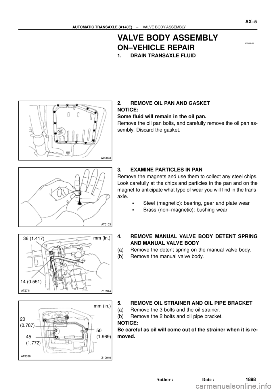
2. REMOVE OIL PAN AND GASKET
NOTICE:
Some fluid will remain in the oil pan.
Remove the oil pan bolts, and carefully remove the oil pan as-
sembly. Discard the gasket.
3. EXAMINE PARTICLES IN PAN
Remove the magnets and use them to collect any steel chips.
Look carefully at the chips and particles in the pan and on the
magnet to anticipate what type of wear you will find in the trans-
axle.
�Steel (magnetic): bearing, gear and plate wear
�Brass (non±magnetic): bushing wear
4. REMOVE MANUAL VALVE BODY DETENT SPRING
AND MANUAL VALVE BODY
(a) Remove the detent spring on the manual valve body.
(b) Remove the manual valve body.
5. REMOVE OIL STRAINER AND OIL PIPE BRACKET
(a) Remove the 3 bolts and the oil strainer.
(b) Remove the 2 bolts and oil pipe bracket.
NOTICE:
Be careful as oil will come out of the strainer when it is re-
moved.
Page 1766 of 4770

Z10940
mm (in.)
20
(0.78)
45
(1.772)50
(1.969)
AT3336
Z10944
mm (in.)
36 (1.417)
14 (0.551)
AT2711
Z10945
Magnets
AT2368
Q00073
AX±8
± AUTOMATIC TRANSAXLE (A140E)VALVE BODY ASSEMBLY
1901 Author�: Date�:
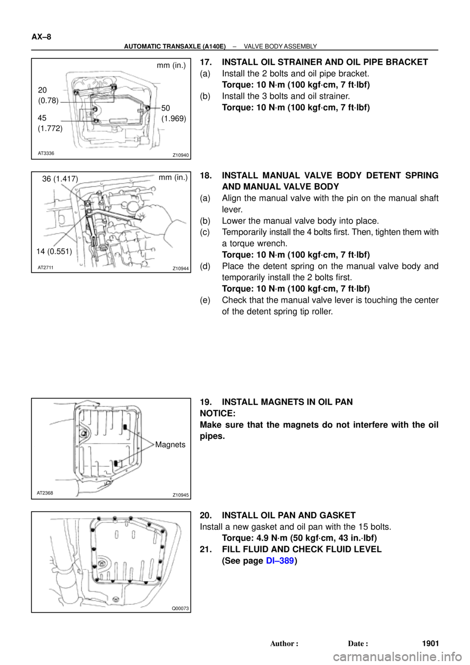
17. INSTALL OIL STRAINER AND OIL PIPE BRACKET
(a) Install the 2 bolts and oil pipe bracket.
Torque: 10 N´m (100 kgf´cm, 7 ft´lbf)
(b) Install the 3 bolts and oil strainer.
Torque: 10 N´m (100 kgf´cm, 7 ft´lbf)
18. INSTALL MANUAL VALVE BODY DETENT SPRING
AND MANUAL VALVE BODY
(a) Align the manual valve with the pin on the manual shaft
lever.
(b) Lower the manual valve body into place.
(c) Temporarily install the 4 bolts first. Then, tighten them with
a torque wrench.
Torque: 10 N´m (100 kgf´cm, 7 ft´lbf)
(d) Place the detent spring on the manual valve body and
temporarily install the 2 bolts first.
Torque: 10 N´m (100 kgf´cm, 7 ft´lbf)
(e) Check that the manual valve lever is touching the center
of the detent spring tip roller.
19. INSTALL MAGNETS IN OIL PAN
NOTICE:
Make sure that the magnets do not interfere with the oil
pipes.
20. INSTALL OIL PAN AND GASKET
Install a new gasket and oil pan with the 15 bolts.
Torque: 4.9 N´m (50 kgf´cm, 43 in.´lbf)
21. FILL FLUID AND CHECK FLUID LEVEL
(See page DI±389)
Page 1775 of 4770
AX03G±01
Q10053
14 (145, 10)
No.1 Exhaust Pipe Support BracketClip Engine Hood
Air Cleaner Assembly
14 (145, 10)
Starter
Cruise Control Actuator
RH Drive Shaft
42 (430, 31)66 (670, 48)
39 (400, 29)
39 (400, 29)
39 (400, 29)
Hold Down Clamp
Manifold Stay
Stiffener
PlateBattery
Battery Tray � Snap Ring
�
32 (330, 24)
27 (280, 20)
Torque Converter
Clutch
x6
42 (430, 31)
42 (430, 31)
Stiffener Plate66 (670, 48)
42 (430, 31)
Exhaust
Manifold Stay66 (670, 48)
� Snap RingLH Drive Shaft
Plug for Line Pressure Test
Rear End Plate
15 (150, 11)
19 (195, 14)
25 (250, 18)
Oil Pan Insulator Shift Control Cable
N´m (kgf´cm, ft´lbf): Specified torque
� Non±reusable partTMMK
TMC
± AUTOMATIC TRANSAXLE (A140E)AUTOMATIC TRANSAXLE UNIT
AX±17
1910 Author�: Date�:
AUTOMATIC TRANSAXLE UNIT
COMPONENTS
Page 1781 of 4770
Q10172
Front
Q10064
Rear
Q10065
TMC : Bolt
TMMK : Nut
± AUTOMATIC TRANSAXLE (A140E)AUTOMATIC TRANSAXLE UNIT
AX±23
1916 Author�: Date�:
(d) Remove the 6 bolts and 4 nuts.
Torque:
19 mm head bolt: 181 N´m (1,850 kgf´cm, 134 ft´lbf)
14 mm head bolt: 32 N´m (330 kgf´cm, 24 ft´lbf)
Nut: 36 N´m (370 kgf´cm, 27 ft´lbf)
(e) Remove the front frame assembly.
33. SUPPORT TRANSAXLE WITH A TRANSMISSION
JACK
34. REMOVE FRONT SIDE STIFFENER PLATE
TMMK made:
Remove the nut, 2 bolts and stiffener plate.
Torque: 42 N´m (430 kgf´cm, 31 ft´lbf)
TMC made:
Remove the 3 bolts and stiffener plate.
Torque: 42 N´m (430 kgf´cm, 31 ft´lbf)
35. REMOVE REAR END PLATE
(a) Remove the 2 bolts and No.1 exhaust pipe support brack-
et.
Torque: 19 N´m (195 kgf´cm, 14 ft´lbf)
(b) Remove the 2 bolts and rear end plate with oil pan insula-
tor.
Torque: 25 N´m (250 kgf´cm, 18 ft´lbf)
Page 1802 of 4770
AUTOMATIC TRANSAXLEPREPARATION ±
AX±6
PREPARATION
SST (SPECIAL SERVICE TOOLS)
09226±10010Crankshaft Front & Rear Bearing
ReplacerInstall RH retainer oil seal
09240±00020Wire Gauge Set
09316±20011Transfer Bearing Replacer
09316±60011Transmission & Transfer Bearing
Replacer
(09316±00011)Replacer Pipe
09350±32014TOYOTA Automatic Transmission
Tool Set
09308±10010Oil Seal Puller
(09351±32032)Counter Driven Gear Holding Tool
(09351±32040)No.1 Piston Spring Compressor
(09351±32050)Snap Ring Expander
(09351±32061)Oil Pump Puller
(09351±32070)No.2 Piston Spring Compressor
(09351±32080)Lock Nut Wrench
AX02L±06
Page 1810 of 4770
AUTOMATIC TRANSAXLECOMPONENT PARTS REMOVAL ±
AX±14
5. REMOVE T/M REVOLUTION SENSOR
(a) Remove the bolt and T/M revolution sensor.
(b) Remove the O±ring from the T/M revolution sensor.
6. REMOVE TRANSAXLE CASE UPPER COVER
7. REMOVE OIL PAN AND GASKET
(a) Remove the 17 bolts.
(b) Remove the oil pan by lifting transaxle case.
NOTICE: Do not turn the transaxle over as this will contami-
nate the valve body with the foreign materials in the bottom
of the oil pan.
(c) Place the transaxle on wooden blocks to prevent damage
to the oil pipe bracket.
8. EXHAUST PARTICLES IN PAN
Remove the magnet and use it to collect any steel chips.
Lock carefully at the chips and particles in the oil pan and
on magnet to anticipate what type of wear you will find in
the transaxle.
�Steel (magnetic): bearing, gear and plate wear
�Brass (non±magnetic): bushing wear
9. REMOVE OIL PIPE BRACKET AND STRAINER
Page 1920 of 4770
AUTOMATIC TRANSAXLECOMPONENT PARTS INSTALLATION ±
AX±124
12. INSTALL MAGNETS IN PLACE
NOTICE: Make sure that the magnets do not interfere with
the oil pipes.
13. INSTALL OIL PAN WITH NEW GASKET
(a) Install a new gasket and oil pan.
(b) Install and torque the 17 bolts.
Torque: 4.9 N´m (50 kgf´cm, 43 in.´lbf)
14. INSTALL THROTTLE CABLE RETAINING PLATE
15. INSTALL TRANSAXLE UPPER COVER
16. INSTALL T/M REVOLUTION SENSOR
(a) Install a new O±ring to the T/M revolution sensor.
(b) Install the T/M revolution sensor with the bolt.
Page 1928 of 4770
AUTOMATIC TRANSAXLESERVICE SPECIFICATIONS ±
AX±132
TORQUE SPECIFICATIONS
Part tightenedN´mkgf´cmft´lbf
Oil cooler pipe union2727520
Oil pan4.95043 in.´lbf
Valve body x Transaxle case1111 08
Accumulator x Cover101007
Oil pump x Transaxle case2222516
O/D case x Transaxle case2525018
Differential LH side bearing retainer1919514
Differential RH retainer1919514
Differential carrier cover3940029
Oil pump body x Stator shaft101007
Ring gear x Differential case1241,26091
Upper valve body x Lower valve body6.66758 in.´lbf
Accumulator cylinder x Valve body6.66758 in.´lbf
Solenoid x Valve body6.66758 in.´lbf
Counter drive gear lock nut2802,855206
Carrire cover x Transaxle case3940029
Parking lock pawl bracket7.47565 in.´lbf
Oil strainer x Transaxle case1111 08
AX04N±03