Page 1553 of 4770
 Install the p")
AC0LX±02
N21046
N21045
Packing Paper
N21044
± AIR CONDITIONINGAIR CONDITIONING UNIT
AC±31
2513 Author�: Date�:
REASSEMBLY
1. INSTALL THERMISTOR TO EVAPORATOR
2. INSTALL EVAPORATOR
(a) Install the plate to the evaporator.
(b) Install the evaporator on the insulator.
(c) Connect the heater case with the 13 screws.
NOTICE:
The packing for water seal should be replaced, with a new
one when the A/C unit is reassembled.
(d) Install the 2 new packings.
(e) Install the grommet to evaporator.
HINT:
If evaporator is replaced, add compressor oil to the compressor.
Add 40 ± 50 cc (1.4 ± 1.7 fl.oz.)
Compressor oil: ND ± OIL 8 or equivalent
3. INSTALL EXPANSION VALVE
(a) Lubricate 2 new O±rings with compressor oil and install
the tubes.
(b) Install the liquid tube and suction tube on the expansion
valve.
(c) Using a knife, cut off packing paper of packing while peel
off the paper, as shown in the illustration.
HINT:
Leave the packing paper untaped on the tube side so that the
installation bolt hole for remains visible.
(d) Apply new packing.
NOTICE:
Do not overtape the packing beyond the expansion valve
edge.
Page 1554 of 4770
N20283
N20245
Pin
Pin AC±32
± AIR CONDITIONINGAIR CONDITIONING UNIT
2514 Author�: Date�:
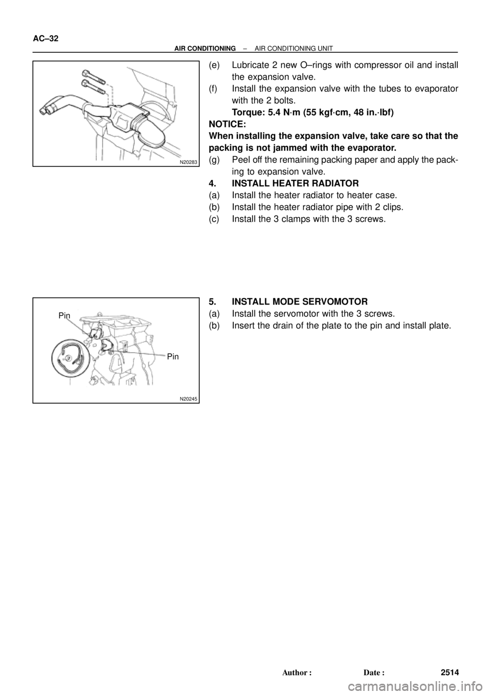
(e) Lubricate 2 new O±rings with compressor oil and install
the expansion valve.
(f) Install the expansion valve with the tubes to evaporator
with the 2 bolts.
Torque: 5.4 N´m (55 kgf´cm, 48 in.´lbf)
NOTICE:
When installing the expansion valve, take care so that the
packing is not jammed with the evaporator.
(g) Peel off the remaining packing paper and apply the pack-
ing to expansion valve.
4. INSTALL HEATER RADIATOR
(a) Install the heater radiator to heater case.
(b) Install the heater radiator pipe with 2 clips.
(c) Install the 3 clamps with the 3 screws.
5. INSTALL MODE SERVOMOTOR
(a) Install the servomotor with the 3 screws.
(b) Insert the drain of the plate to the pin and install plate.
Page 1583 of 4770
AC0MO±02
N21046
N21045
N21044
± AIR CONDITIONINGEXPANSION VALVE
AC±61
2543 Author�: Date�:
INSTALLATION
1. INSTALL LIQUID TUBE AND SUCTION TUBE TO EX-
PANSION VALVE
HINT:
Lubricate 4 new O±rings with compressor oil and install the
tubes.
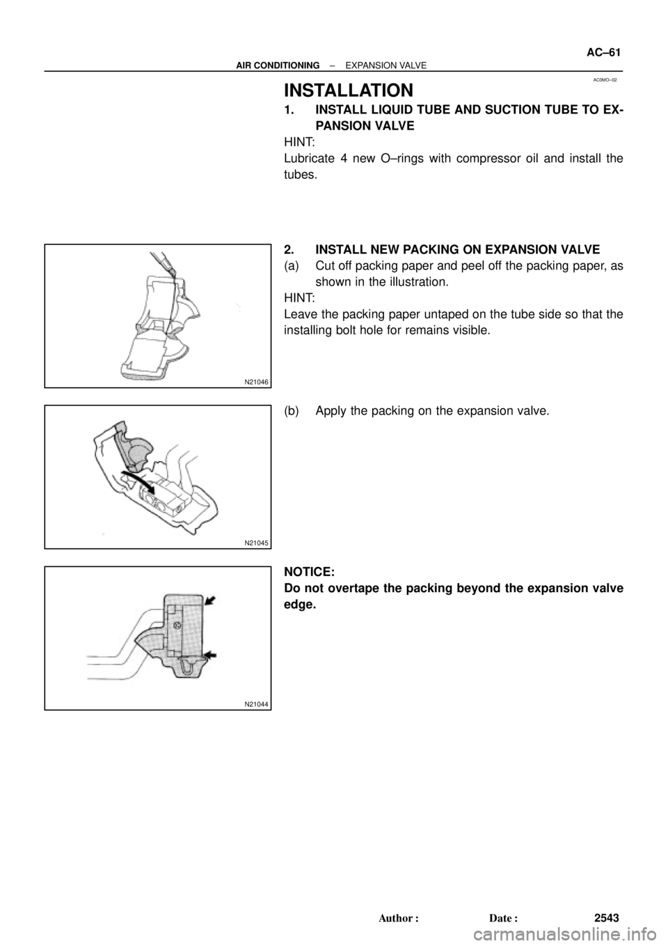
2. INSTALL NEW PACKING ON EXPANSION VALVE
(a) Cut off packing paper and peel off the packing paper, as
shown in the illustration.
HINT:
Leave the packing paper untaped on the tube side so that the
installing bolt hole for remains visible.
(b) Apply the packing on the expansion valve.
NOTICE:
Do not overtape the packing beyond the expansion valve
edge.
Page 1584 of 4770
N20246
AC±62
± AIR CONDITIONINGEXPANSION VALVE
2544 Author�: Date�:
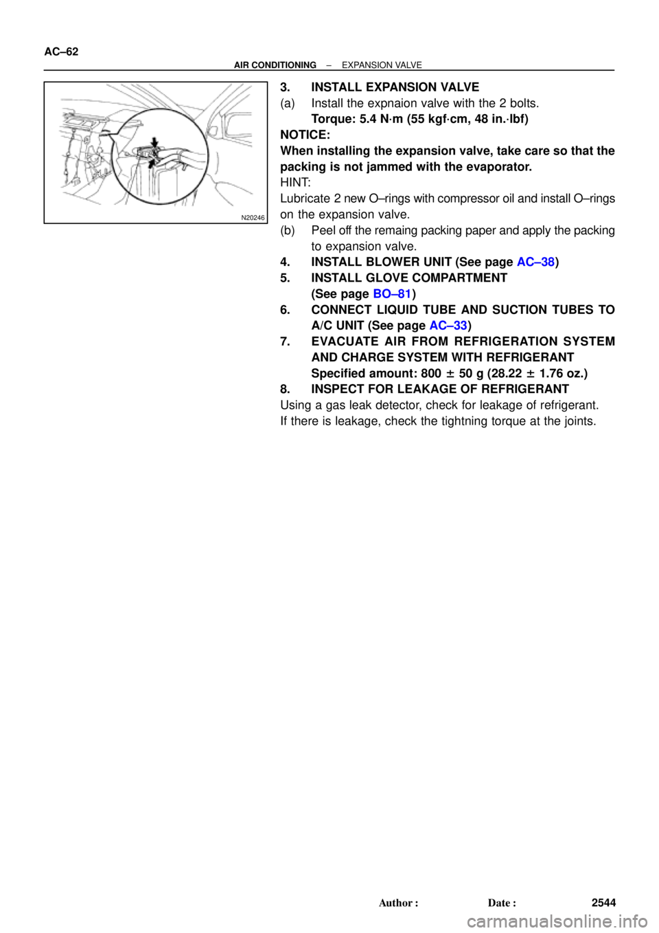
3. INSTALL EXPANSION VALVE
(a) Install the expnaion valve with the 2 bolts.
Torque: 5.4 N´m (55 kgf´cm, 48 in.´lbf)
NOTICE:
When installing the expansion valve, take care so that the
packing is not jammed with the evaporator.
HINT:
Lubricate 2 new O±rings with compressor oil and install O±rings
on the expansion valve.
(b) Peel off the remaing packing paper and apply the packing
to expansion valve.
4. INSTALL BLOWER UNIT (See page AC±38)
5. INSTALL GLOVE COMPARTMENT
(See page BO±81)
6. CONNECT LIQUID TUBE AND SUCTION TUBES TO
A/C UNIT (See page AC±33)
7. EVACUATE AIR FROM REFRIGERATION SYSTEM
AND CHARGE SYSTEM WITH REFRIGERANT
Specified amount: 800 ± 50 g (28.22 ± 1.76 oz.)
8. INSPECT FOR LEAKAGE OF REFRIGERANT
Using a gas leak detector, check for leakage of refrigerant.
If there is leakage, check the tightning torque at the joints.
Page 1633 of 4770
AUTOMATIC TRANSAXLESERVICE SPECIFICATIONS ±
AX±18
TORQUE SPECIFICATION
Part tightenedN´mkgf´cmft´lbf
Stator shaft x Oil pump body101007
Upper valve body x Lower valve body5.45548
Ring gear x Differential case9798571
Side bearing cap x Transaxle case7273053
Bearing retainer x Transaxle case1919514
Counter drive gear x Drive pinion1721,750127
Carrier cover x Transaxle case2525018
Parking lock pawl bracket7.47565 in.´lbf
Overdrive case x Transaxle case2526019
Oil pump x Transaxle case2222016
Valve body x Transaxle case101007
Manual valve body x Transaxle case101007
Detent spring x Valve body101007
Oil tube bracket x Transaxle case101007
Oil strainer x Valve body101007
Oil pan x Transaxle case4.95043 in.´lbf
Park/Neutral position switch6.97061 in.´lbf
Park/Neutral position switch adjusting bolt5.45548 in.´lbf
Union2727520
AT06Q±0C
Page 1641 of 4770
AUTOMATIC TRANSAXLEPREPARATION ±
AX±8
PREPARATION
SST (SPECIAL SERVICE TOOLS)
09240±00020Wire Gauge Set
09330±00021Companion Flange Holding Tool
09350±32014TOYOTA Automatic Transmission
Tool Set
09308±10010Oil Seal Puller
(09351±32020)Stator Stopper
(09351±32032)Counter Driven Gear Holding Tool
(09351±32040)No.1 Piston Spring Compressor
(09351±32050)Snap Ring Expander
(09351±32061)Oil Pump Puller
(09351±32070)No.2 Piston Spring Compressor
(09351±32080)Lock Nut Wrench
(09351±32090)Oil Seal Remover & Replacer
(09351±32100)Drive Pinion Bearing Replacer
AX0EQ±02
Page 1649 of 4770
AUTOMATIC TRANSAXLECOMPONENT PARTS REMOVAL ±
AX±16
(b) Remove the cover.
7. REMOVE OIL PAN AND GASKET
(a) Remove the 15 bolts.
(b) Remove the oil pan by lifting transaxle case.
NOTICE: Do not turn the transaxle over as this will contami-
nate the valve body with the foreign materials in the bottom
of the oil pan.
(c) Place the transaxle on wooden blocks to prevent damage
to the tube bracket.
8. EXAMINE PARTICLES IN PAN
Remove the magnets and use them to collect any steel
chips. Look carefully at the chips and particles in the oil
pan and on the magnets to anticipate what type of wear
you will find in the transmission:
Steel (magnetic): bearing, gear and plate wear
Brass (non±magnetic): bushing wear
9. DISCONNECT NO.1 AND NO.2 SOLENOID CONNEC-
TORS
10. REMOVE TUBE BRACKET AND OIL STRAINER
Page 1756 of 4770
AUTOMATIC TRANSAXLECOMPONENT PARTS INSTALLATION ±
AX±123
48. CONNECT SOLENOID WIRING
(a) Connect the No.1 solenoid connector. (white and shorter
wire)
(b) Connect the No.2 solenoid connector. (black and longer
wire)
49. INSTALL 3 MAGNETS IN PLACE
NOTICE: Make sure that the magnets do not interfere with
the oil tubes.
50. INSTALL OIL PAN WITH NEW GASKET
Torque: 4.9 N´m (50 kgf´cm, 43 in.´lbf)
51. INSTALL COVER
52. INSTALL COVER BRACKET


09240±00020Wire Gauge Set
09330±00021Companion Flange Holding Tool
09350±32014TOYOTA Automatic Transmission
Tool Set")
 Remove the cover.
7. REMOVE OIL PAN AND GASKET
(a) Remove the 15 bolts.
(b) Remove the oil pan by lifting transaxle case.
NOTICE: Do not turn t")
 Connect the No.1 solenoid connector. (white and shorter
wire)
(b) Connect the No.2 solenoid connector. (bla")