Page 1935 of 4770
VALVE BODY ASSEMBLY
AX±7
1927 Author�: Date�:
VALVE BODY ASSEMBLY
ON±VEHICLE REPAIR
1. DRAIN ATF
Using a hexagon wrench,")
AX03Q±02
AT3785
AT0103
D01019
Q05728
Connector
± AUTOMATIC TRANSAXLE (A541E)VALVE BODY ASSEMBLY
AX±7
1927 Author�: Date�:
VALVE BODY ASSEMBLY
ON±VEHICLE REPAIR
1. DRAIN ATF
Using a hexagon wrench, remove the drain plug and fluid into
the suitable container.
2. REMOVE OIL PAN AND GASKET
NOTICE:
Some fluid will remain in the oil pan.
Remove oil pan bolts, and carefully remove the pan assembly.
Discard the gasket.
3. EXAMINE PARTICLES IN PAN
Remove the magnets and use them to collect any steel chips.
Look at the chips and particles in the pan and magnet carefully
to anticipate what type of wear you will find in the transaxle.
�Steel (magnetic): bearing, gear and plate wear
�Brass (non±magnetic): bushing wear
4. REMOVE OIL STRAINER AND APPLY PIPE BRACKET
(a) Remove the 3 bolts and oil strainer.
NOTICE:
Be careful as oil will come out of the strainer when it is re-
moved.
(b) Remove the 3 bolts and apply pipe bracket.
5. REMOVE OIL PIPES
Pry up both pipe ends with a large screwdriver and remove the
5 pipes.
6. DISCONNECT SOLENOID CONNECTORS
Page 1940 of 4770
Z19256
BA
B A
AT3741
AT3785
AX±12
± AUTOMATIC TRANSAXLE (A541E)VALVE BODY ASSEMBLY
1932 Author�: Date�:
23. INSTALL OIL STRAINER AND APPLY PIPE BRACKET
(a) Install the oil strainer and apply pipe bracket.
(b) Install and torque the 6 bolts.
Bolt length:
Bolt A: 22 mm (0.866 in.)
Bolt B: 53 mm (2.087 in.)
Torque:
Bolt A: 10 N´m (100 kgf´cm, 7 ft´lbf)
Bolt B: 11 N´m (110 kgf´cm, 8 ft´lbf)
24. INSTALL MAGNETS IN PLACE
Install the 3 magnets in the indentations of the oil pan, as shown
in the illustration.
NOTICE:
Make sure that the magnet does not interfere with the oil
pipes.
25. INSTALL OIL PAN AND GASKET
(a) Install the oil pan and a new gasket.
(b) Install and torque the 17 new bolts.
Torque: 7.8 N´m (80 kgf´cm, 69 in.´lbf)
26. INSTALL AND TORQUE DRAIN PLUG
Torque: 49 N´m (500 kgf´cm, 36 ft´lbf)
27. FILL ATF AND CHECK FLUID LEVEL
(See page DI±438)
Page 2221 of 4770
BE0B3±06
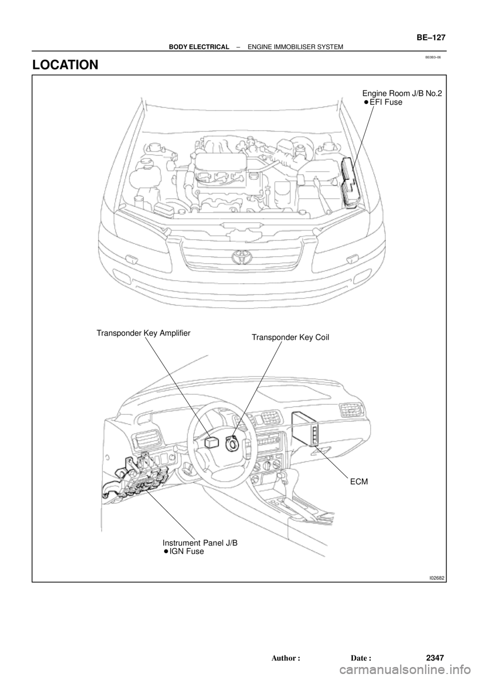
I02682
Engine Room J/B No.2
� EFI Fuse
Transponder Key Amplifier
Transponder Key Coil
ECM
� IGN Fuse Instrument Panel J/B
± BODY ELECTRICALENGINE IMMOBILISER SYSTEM
BE±127
2347 Author�: Date�:
LOCATION
Page 2584 of 4770

A07122
IG Switch
B±R
BatteryEngine Room
J/B No.2
76B±R13
1II3B±R
B
BR
Spark Plug
Spark Plug
2
3 2
3 4
Tr2 Igniter
No.1
Ignition
Coil
No.1
FL Block
Y±R
BR
B
20
19
IGT2
Tr1
E9
E9
E9
W±R
IGT1
IGF5 V
Tr1
Ignition Coil
No.2
Igniter
No.2
AA A
EC
Tr2
W±R
B±R 5 51B 1K
Instrument
W±R
W±R
2L 2A
4 1
AM2B
F4 F6 1
1
B±G
MAIN FL
3 1
4
J/C J25
*1: w/o Immobiliser
*2: w/ Immobiliser(*1) (*2)
ECM
E9 23
E9 22
E9 17
(*1) (*2)
W±R
Panel J/BB
B
BR
BR J19
J/C
DI±164
± DIAGNOSTICSENGINE (5S±FE)
399 Author�: Date�:
WIRING DIAGRAM
INSPECTION PROCEDURE
HINT:
�If DTC P1300 is displayed, check ignition coil No.1 circuit.
�If DTC P1300 is displayed, check ignition coil No.2 circuit.
�Read freeze frame data using TOYOTA hand±held tester or OBD II scan tool. Because freeze frame
records the engine conditions when the malfunction is detected, when troubleshooting it is useful for
determining whether the vehicle was running or stopped, the engine warmed up or not, the air±fuel
ratio lean or rich, etc. at the time of the malfunction.
1 Check for spark plug and spark of misifining cylinder (See page DI±89).
NG Go to step 4.
OK
2 Check for open and short in harness and connector in IGF signal circuit between
ECM and ignition coils (See page IN±31).
NG Repair or replace harness or connector.
OK
Page 2599 of 4770
A07554
ECM
+B 12
E7 B±Y J/C
B
J28 J27B
B±Y
Instrument
Panel J/B 22J 2K7
W±R EFI
Relay 1 3
52
2F4
W±B
2A 1
AM2
42L
B
FL
Block
MAIN
FL
B±GEngine
J/B No.2
5
1B
531K71W
IGN
1K
Room
W±R
IG
Switch
7 6
14
E9
BR
B±R
EC
E1
F6
F4EB
B±R
1
1
EFI
J23
J/C A
A
Battery
BR
(*2) (*1)
*1: w/ Immobiliser
*2: w/o ImmobiliserE924 (*2)
MREL 7
E10 B±Y (*1) 6II4 B±W (*1)
± DIAGNOSTICSENGINE (5S±FE)
DI±179
414 Author�: Date�:
ECM Power Source Circuit
CIRCUIT DESCRIPTION
When the ignition switch is turned ON, battery positive voltage is applied to the coil, closing the contacts of
the EFI main relay (Marking: EFI) and supplying power to terminal +B of the ECM.
WIRING DIAGRAM
DI01L±05
Page 2772 of 4770
S05723
J18
Junction
Connector
A
A A A AII3B±R
B±R B±R W±R128 3
1K 1C
Ignition
Switch
76
1K
1BB±R
G
B±R
B±R Y
LIgnition Coil
Spark Plug
No.1
No.2
No.3
11
12
2
2
ED
BR
3 2 1
10
9
7
6
5
4
W±R LG±B
BR±Y
IgniterECM
IGT1
IGT2
IGT3
IGF5 VInstrument
Panel J/B
E1125
E1113
E1112
E1111GR
B±R
5
5
W±R
Engine Room J/B
2L4
AM2
2A1
B
Fusible
Link
Block 1
1
F6
B±GFL
MAIN
Battery
F4
Instrument
Panel J/B
DI±352
± DIAGNOSTICSENGINE (1MZ±FE)
587 Author�: Date�:
WIRING DIAGRAM
INSPECTION PROCEDURE
HINT:
Read freeze frame data using TOYOTA hand±held tester or OBD II scan tool. Because freeze frame records
the engine conditions when the malfunction is detected, when troubleshooting it is useful for determining
whether the vehicle was running or stopped, the engine warmed up or not, the air±fuel ratio lean or rich, etc.
at the time of the malfunction.
1 Check spark plug and spark of misfiring cylinder (See page DI±276).
NG Go to step 4.
OK
Page 2789 of 4770

A07450
Ignition SwitchW±R B±RInstrument Panel J/B
FL
MAINFusible
Link
Block
BatteryJunction
ConnectorECM
B±R
W±R
BR
BR
W±B
B±Y
B
6
7
2 4
17
2 5
4
1 1B
AA F4 F6 E10E7
2F 2K 2J
2L
2AEFI EFI
RelayEngine Room
J/B+B
E1 17 16
AM2
EB EC
J28
3
1E72
MREL
E78IGSW
J27
1W
1B7
5 IGN
1K3
1K5
B+ B
B±Y
B±W
B±W
J35 J35
C
C
Junction
Connector
B±GJ22
Junction
Connector
± DIAGNOSTICSENGINE (1MZ±FE)
DI±369
604 Author�: Date�:
ECM Power Source Circuit
CIRCUIT INSPECTION
When the ignition switch is turned on, battery positive voltage is applied to terminal IGSW of the ECM and
the EFI main relay (Marking: EFI) control circuit in the ECM sends a signal to terminal MREL of the ECM
switching on the EFI main relay.
This signal causes current to flow to the coil, closing the contacts of the EFI, main relay and supplying power
to terminals +B of the ECM.
If the ignition switch is turned off, the ECM continues to switch on the EFI main relay for a maximum of 2
seconds for the initial setting of the IAC valve.
WIRING DIAGRAM
DI4DU±01
Page 2831 of 4770

DI±411
646 Author�: Date�:
DTC P0750, P0755 Shift Solenoid A/B Malfunction
(Shift Solenoid Valve No.1/No.2)
SYSTEM DESCRIPTION
The ECM uses signals fr")
Q07741
± DIAGNOSTICSAUTOMATIC TRANSAXLE (A140E)
DI±411
646 Author�: Date�:
DTC P0750, P0755 Shift Solenoid A/B Malfunction
(Shift Solenoid Valve No.1/No.2)
SYSTEM DESCRIPTION
The ECM uses signals from the vehicle speed sensor and crankshaft position sensor to detect the actual
gear position (1st, 2nd, 3rd or O/D gear).
Then the ECM compares the actual gear with the shift schedule in the ECM memory to detect mechanical
trouble of the shift solenoid valves, valve body or automatic transaxle (clutch, brake or gear etc.).
DTC No.DTC Detecting ConditionTrouble Area
P0750
P0755During normal driving, the gear required by the ECM does not
match the actual gear
(2 trip detection logic)�Shift solenoid valve No.1/No.2 is stuck open or closed
�Valve body is blocked up or stuck
�Automatic transaxle (clutch, brake or gear etc.)
Check the shift solenoid valve No.1 when DTC P0750 is output and check the shift solenoid valve No.2 when
DTC P0755 is output.
INSPECTION PROCEDURE
1 Check shift solenoid valve No.1 or No.2 operation.
PREPARATION:
(a) Remove the oil pan.
(b) Remove the shift solenoid valve No.1 or No.2.
CHECK:
(a) By applying 490 kPa (5 kgf/cm2, 71 psi) of compressed
air, check that the solenoid valve does not leak air.
(b) When battery positive voltage is supplied to the shift sole-
noid valve, check that the valve opens.
OK:
(a) Solenoid valve does not leak air.
(b) Solenoid valve opens.
NG Replace the shift solenoid valve No.1 or No.2.
OK
DI032±02