Page 3762 of 4770

MX04C±01
Q09998
Hood
ClipCruise Control Actuator
Control Cable
Clutch Line
Bracket
Clutch Release CylinderWasher
RH Drive Shaft
Snap Ring
RH Stiffener
Plate
Ground Cable
Starter
Battery
Snap Ring
LH Drive Shaft�
RH Fender Apron
Seal
LH Stiffener Plate
Manifold StayTransaxle Back±Up Light Switch
Connector
Rear End Plate with Oil Pan
InsulatorAir Cleaner
Case Assembly
with Air Hose
Vehicle Speed Sensor
Connector
No.1 Fuel Tube Protector Engine LH
Mounting Insulator
with Bracket
Rear RH Suspension Member Brace
PS Gear Assembly
Lock Cap
Rear LH Suspension Member Brace Manifold StayClip
LH Fender Apron
Seal
Suspension Member with
Lower Suspension Arm
Front RH Suspension
Member BraceStabilizer Bar Link
Front Exhaust PipeCotter Pin
RH Fender
Liner
LH Fender Liner
Exhaust Pipe BracketNo.1 Exhaust Pipe
Support Bracket
: Specified torque
Non±reusable partGasket w/ Cruise Control:
�
�
�
Cotter Pin
�
Hole
Plug
�
�
Engine Rear Side Shutter PlateHold±Down
Clamp
Hole
Plug
12 (120, 9)
13 (130, 9)
46 (470, 34)
39 (400, 29)
6.9 (70, 61 in.´lbf)
14 (145, 10)
12 (120, 9)
39 (400, 29)
39 (400, 29)
64 (650, 47)
56 (570, 41)
37 (380, 27)
9.3 (95, 82 in.´lbf)
42 (425, 31)
32 (330, 24)
Silver Bolt: 44 (450, 33)
Green Bolt: 66 (670, 48)
62 (630, 46)
64 (650, 47)
64 (650, 47)
37 (380, 27)
181 (1,850, 134)
181 (1,850, 134)
181 (1,850, 134)
36 (370, 27)
10 (100, 7)
32 (330, 24)19 (195, 14)
49 (500, 36)
294 (3,000, 217)
Silver Bolt: 44 (450, 33)
Green Bolt: 66 (670, 48)
36 (370, 27)66 (670, 48)
39 (400, 29)
127 (1,300, 94)
33 (330, 24)
33 (330, 24)
19 (195, 14)
80 (820, 59)
Gasket�
�� �
Steering Return Pipe
Front LH
Suspension
Member Brace
N´m (kgf´cm, ft´lbf)
± MANUAL TRANSAXLE (S51)MANUAL TRANSAXLE UNIT
MX±3
1853 Author�: Date�:
MANUAL TRANSAXLE UNIT
COMPONENTS
Page 3766 of 4770
MANUAL TRANSAXLE UNIT
MX±7
1857 Author�: Date�:
23. REMOVE FRONT SUSPENSION MEMBER WITH LOW-
ER SUSPENSION ARM
(a) Remove the LH and RH f")
Q10008
C
C
A
CBA
ABC A
Q10011
Q10009
± MANUAL TRANSAXLE (S51)MANUAL TRANSAXLE UNIT
MX±7
1857 Author�: Date�:
23. REMOVE FRONT SUSPENSION MEMBER WITH LOW-
ER SUSPENSION ARM
(a) Remove the LH and RH fender liner set screws.
(b) Remove the 6 bolts, 4 nuts, front LH and RH suspension
member braces, rear LH and RH suspension member
braces and front suspension member with the lower sus-
pension arm.
Torque:
Bolt A: 181 N´m (1,850 kgf´cm, 134 ft´lbf)
Bolt B: 32 N´m (330 kgf´cm, 24 ft´lbf)
Nut C: 36 N´m (370 kgf´cm, 27 ft´lbf)
24. JACK UP TRANSAXLE SLIGHTLY
Using a transmission jack, support the transaxle.
25. REMOVE LH STIFFENER PLATE
Remove the 3 bolts and LH stiffener plate.
Torque: 37 N´m (380 kgf´cm, 27 ft´lbf)
26. REMOVE REAR END PLATE WITH OIL PAN INSULA-
TOR AND RH STIFFENER PLATE
(a) Remove the 2 bolts and rear end plate with the oil pan in-
sulator.
Torque: 9.3 N´m (95 kgf´cm, 82 in.´lbf)
(b) Remove the 2 bolts and manifold stay.
Torque: 39 N´m (400 kgf´cm, 29 ft´lbf)
(c) Remove the 4 bolts and RH stiffener plate.
Torque: 39 N´m (400 kgf´cm, 29 ft´lbf)
27. REMOVE TRANSAXLE
Lower the engine left side and remove the transaxle from the
engine.
HINT:
At the time of installation, please refer to the following items.
�Align the input shaft with the clutch disc and install the
transaxle to the engine.
�Temporarily tighten the transaxle mounting bolts.
Page 3785 of 4770
SM0189
SM0190
SM0049
SST
SM0050
MX±26
± MANUAL TRANSAXLE (S51)INPUT SHAFT
1876 Author�: Date�:
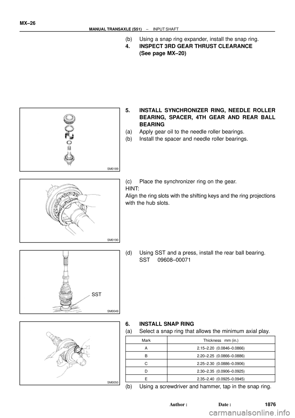
(b) Using a snap ring expander, install the snap ring.
4. INSPECT 3RD GEAR THRUST CLEARANCE
(See page MX±20)
5. INSTALL SYNCHRONIZER RING, NEEDLE ROLLER
BEARING, SPACER, 4TH GEAR AND REAR BALL
BEARING
(a) Apply gear oil to the needle roller bearings.
(b) Install the spacer and needle roller bearings.
(c) Place the synchronizer ring on the gear.
HINT:
Align the ring slots with the shifting keys and the ring projections
with the hub slots.
(d) Using SST and a press, install the rear ball bearing.
SST 09608±00071
6. INSTALL SNAP RING
(a) Select a snap ring that allows the minimum axial play.
MarkThickness mm (in.)
A2.15±2.20 (0.0846±0.0866)
B2.20±2.25 (0.0866±0.0886)
C2.25±2.30 (0.0886±0.0906)
D2.30±2.35 (0.0906±0.0925)
E2.35±2.40 (0.0925±0.0945)
(b) Using a screwdriver and hammer, tap in the snap ring.
Page 3838 of 4770
OUTPUT SHAFT
1837 Author�: Date�:
REASSEMBLY
HINT:
Coat all of the sliding and rotating surfaces with gear oil before
r")
MX05D±01
Q00384
Front
Z00225
Z00385
SST
Z00386
MX±36
± MANUAL TRANSAXLE (E153)OUTPUT SHAFT
1837 Author�: Date�:
REASSEMBLY
HINT:
Coat all of the sliding and rotating surfaces with gear oil before
reassembly.
1. INSTALL NO.1 CLUTCH HUB INTO HUB SLEEVE
(a) Install the clutch hub and shifting keys to the hub sleeve.
(b) Install the shifting key springs under the shifting keys.
NOTICE:
Position the key springs so that their end gaps are not
aligned.
2. INSTALL NEEDLE ROLLER BEARING, 1ST GEAR,
SYNCHRONIZER RING AND NO.1 HUB SLEEVE TO
OUTPUT SHAFT
(a) Apply MP grease to the needle roller bearing.
(b) Install the 1st gear.
(c) Place the synchronizer ring (for the 1st gear) on the gear
and align the ring slots with the shifting keys.
(d) Using SST and a press, install the 1st gear and No.1 hub
sleeve.
SST 09316±60011 (09316±00041)
3. INSTALL SNAP RING
(a) Select a snap ring that allows the minimum axial play.
MarkThickness mm (in.)MarkThickness mm (in.)
A2.80 (0.1102)E3.00 (0.1181)
B2.85 (0.1122)F3.05 (0.1201)
C2.90 (0.1142)G3.10 (0.1220)
D2.95 (0.1161)±±
(b) Using a snap ring expander, install the snap ring.
Page 3860 of 4770
± PREPARATIONENGINE MECHANICAL (1MZ±FE)
PP±9
61 Author�: Date�:
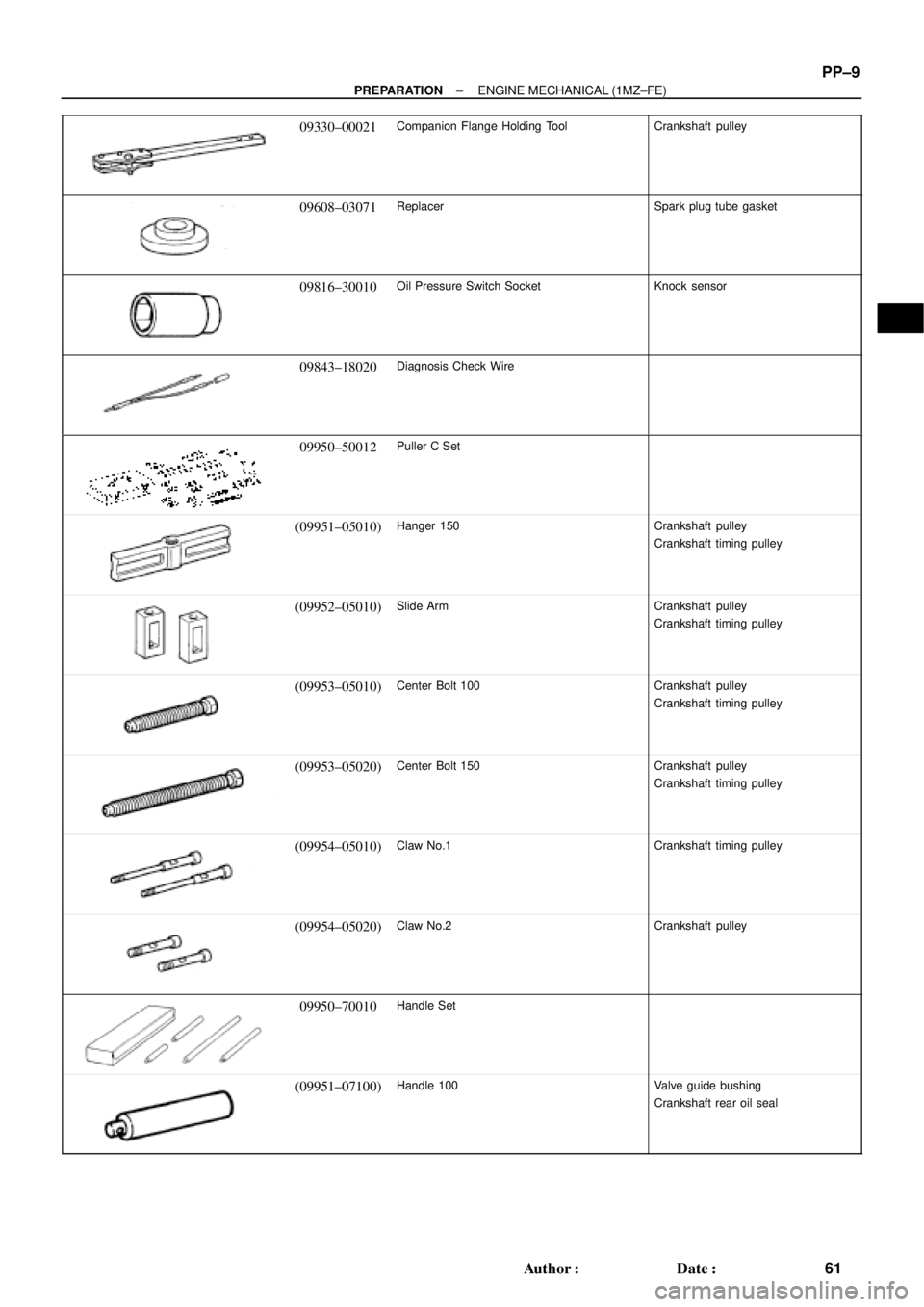
09330±00021Companion Flange Holding ToolCrankshaft pulley
09608±03071ReplacerSpark plug tube gasket
09816±30010Oil Pressure Switch SocketKnock sensor
09843±18020Diagnosis Check Wire
09950±50012Puller C Set
(09951±05010)Hanger 150Crankshaft pulley
Crankshaft timing pulley
(09952±05010)Slide ArmCrankshaft pulley
Crankshaft timing pulley
(09953±05010)Center Bolt 100Crankshaft pulley
Crankshaft timing pulley
(09953±05020)Center Bolt 150Crankshaft pulley
Crankshaft timing pulley
(09954±05010)Claw No.1Crankshaft timing pulley
(09954±05020)Claw No.2Crankshaft pulley
09950±70010Handle Set
(09951±07100)Handle 100Valve guide bushing
Crankshaft rear oil seal
Page 3883 of 4770
PP0K3±04
PP±32
± PREPARATIONLUBRICATION (5S±FE)
84 Author�: Date�:
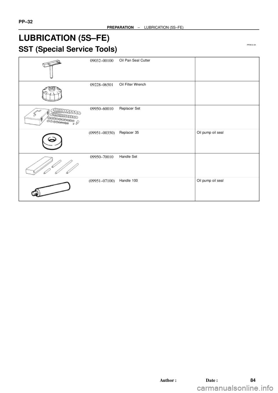
LUBRICATION (5S±FE)
SST (Special Service Tools)
09032±00100Oil Pan Seal Cutter
09228±06501Oil Filter Wrench
09950±60010Replacer Set
(09951±00350)Replacer 35Oil pump oil seal
09950±70010Handle Set
(09951±07100)Handle 100Oil pump oil seal
Page 3887 of 4770
PP1WC±01
PP±36
± PREPARATIONLUBRICATION (5S±FE)
88 Author�: Date�:
SSM (Special Service Materials)
08826±00080Seal Packing Black or equivalent
(FIPG)Oil pan
08833±00080Adhesive 1344
THREE BOND 1344
LOCTITE 242 or equivalentOil pressure switch
Page 3888 of 4770
PP0C4±03
± PREPARATIONLUBRICATION (1MZ±FE)
PP±37
89 Author�: Date�:
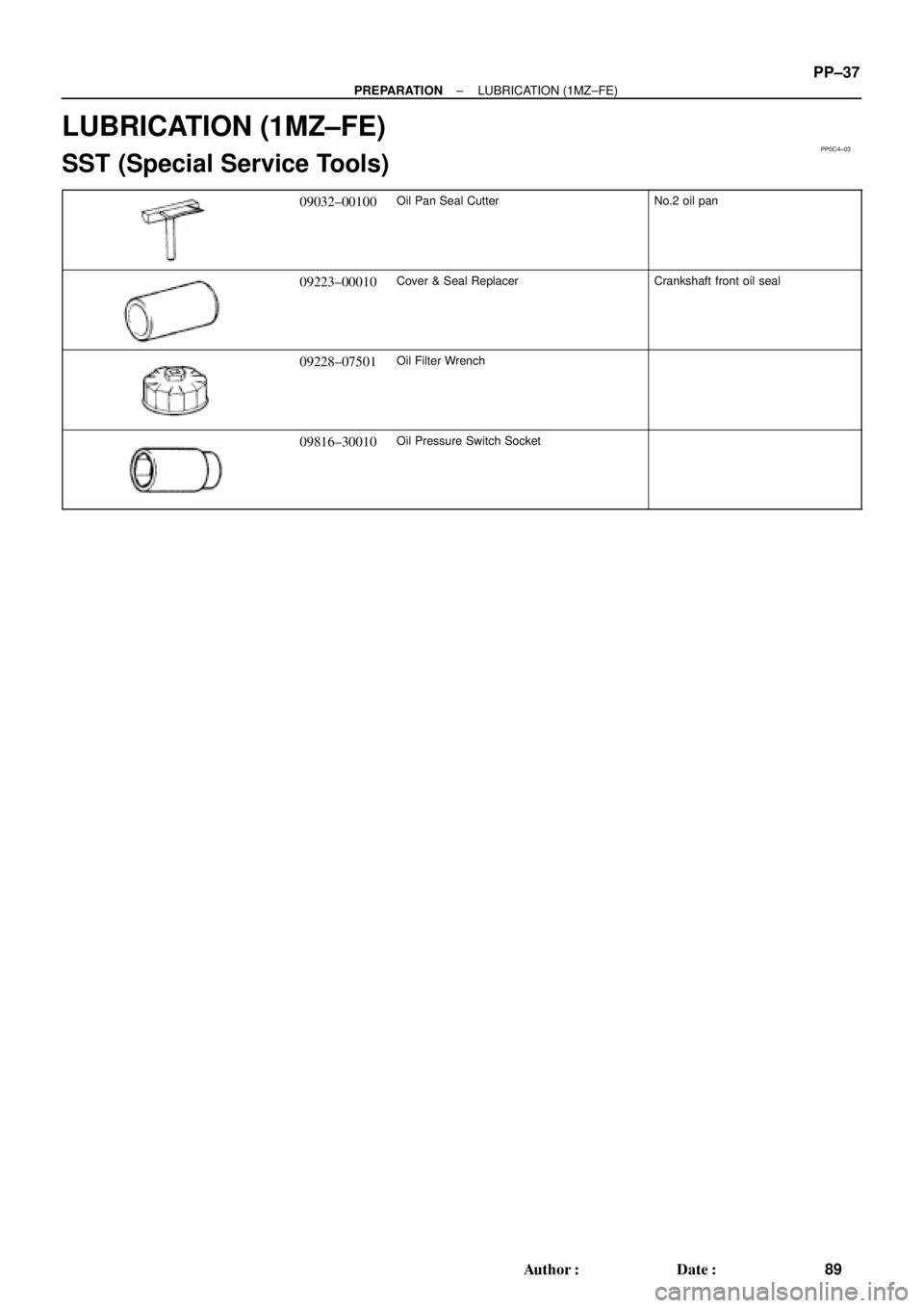
LUBRICATION (1MZ±FE)
SST (Special Service Tools)
09032±00100Oil Pan Seal CutterNo.2 oil pan
09223±00010Cover & Seal ReplacerCrankshaft front oil seal
09228±07501Oil Filter Wrench
09816±30010Oil Pressure Switch Socket