Page 3475 of 4770
A07354
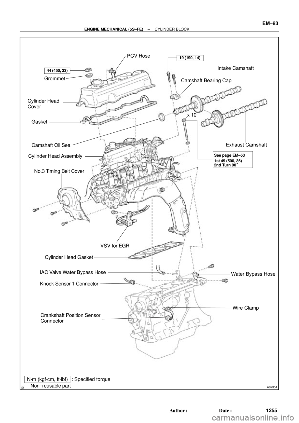
Grommet
Cylinder Head
Cover
Gasket
� Camshaft Oil Seal
Cylinder Head Assembly
No.3 Timing Belt Cover
Crankshaft Position Sensor
ConnectorWire Clamp Water Bypass Hose Exhaust Camshaft Intake Camshaft
Camshaft Bearing Cap PCV Hose
� Cylinder Head Gasket
IAC Valve Water Bypass Hose
Knock Sensor 1 Connector
N´m (kgf´cm, ft´lbf)
� Non±reusable part
44 (450, 33)
19 (190, 14)
VSV for EGR
: Specified torquex 10
1st 49 (500, 36)
2nd Turn 90° See page EM±53
± ENGINE MECHANICAL (5S±FE)CYLINDER BLOCK
EM±83
1255 Author�: Date�:
Page 3478 of 4770
CYLINDER BLOCK
1258 Author�: Date�:
DISASSEMBLY
1. INSTALL ENGINE TO ENGINE STAND FOR DIS-
ASSEMBLY
2. REMOVE TIMING BELT AND PULLEYS
(See pa")
EM0YW±01
S06011
1
3
2 EM±86
± ENGINE MECHANICAL (5S±FE)CYLINDER BLOCK
1258 Author�: Date�:
DISASSEMBLY
1. INSTALL ENGINE TO ENGINE STAND FOR DIS-
ASSEMBLY
2. REMOVE TIMING BELT AND PULLEYS
(See page EM±17)
3. REMOVE CYLINDER HEAD ASSEMBLY
(a) Remove the 3 bolts and No.3 timing belt cover.
(b) Remove the cylinder head cover.
(1) Disconnect the PCV hose from the intake manifold.
(2) Remove the 4 nuts, 4 grommets, head cover and
gasket.
(c) Remove the camshafts. (See page EM±33)
(d) Disconnect the knock sensor 1 connector.
(e) Disconnect the crankshaft position sensor connector.
(f) Disconnect the wire clamp from the generator drive belt
adjusting bar.
(g) Disconnect the IAC valve water bypass hose from the wa-
ter bypass pipe.
(h) Disconnect the water bypass hose (from the water by-
pass pipe) from the water outlet.
(i) Remove the bolt holding the VSV for EGR to the intake
manifold.
(j) Remove the 2 bolts holding the water bypass pipe to the
cylinder head.
(k) Remove the cylinder head assembly.
(See page EM±33)
4. REMOVE OIL DIPSTICK
5. REMOVE OIL PAN AND OIL PUMP
(a) Disconnect the crankshaft position sensor connector
from the generator drive belt adjusting bar.
(b) Remove the oil pan and oil pump. (See page LU±7)
6. REMOVE PS PUMP BRACKET
Remove the 3 bolts and pump bracket.
7. REMOVE KNOCK SENSOR 1 (See page SF±57)
8. REMOVE OIL FILTER (See page LU±2)
9. REMOVE WATER PUMP, WATER BYPASS PIPE AND
OIL COOLER (w/ OIL COOLER) ASSEMBLY
(a) w/ Oil Cooler:
Remove the nut and union bolt, and disconnect the oil
cooler. Remove the O±ring.
(b) Remove the bolt and generator drive belt adjusting bar.
(c) Remove the 3 bolts in the sequence shown, remove the
water pump, water bypass pipe, oil cooler (w/ oil cooler)
assembly and O±ring.
Page 3505 of 4770
± ENGINE MECHANICAL (5S±FE)CYLINDER BLOCK
EM±113
1285 Author�: Date�:
(f) Install the wire clamp to the generator drive belt adjusting
bar.
(g) Connect the IAC valve water bypass hose to the water by-
pass pipe.
(h) Connect the water bypass hose (from the water bypass
pipe) to the water outlet.
(i) Install the camshafts. (See page EM±53)
(j) Install the cylinder head cover.
(1) Install the cylinder head cover. (See page EM±53)
(2) Connect the PCV hose to the intake manifold.
(k) Install the No.3 timing belt cover with the 3 bolts.
Torque: 7.8 N´m (80 kgf´cm, 69 in.´lbf)
23. INSTALL TIMING BELT AND PULLEYS
(See page EM±23)
24. DISCONNECT ENGINE FROM ENGINE STAND
Page 3510 of 4770
VALVE CLEARANCE
1290 Author�: Date�:
VALVE CLEARANCE
INSPECTION
HINT:
Inspect and adjust the val")
EM04K±04
P18805
P13074
RH EX
RH IN
LH IN
LH EX 13
6
23
1
6
2Front EM±4
± ENGINE MECHANICAL (1MZ±FE)VALVE CLEARANCE
1290 Author�: Date�:
VALVE CLEARANCE
INSPECTION
HINT:
Inspect and adjust the valve clearance when the engine is cold.
1. REMOVE RH FENDER APRON SEAL
2. DRAIN ENGINE COOLANT
3. REMOVE V±BANK COVER
(a) Using a 5 mm hexagon wrench, remove the 2 nuts.
(b) Disconnect the 2 clips, and remove the cover.
4. REMOVE HIGH±TENSION CODE SET
(See page IG±7)
5. REMOVE AIR INTAKE CHAMBER ASSEMBLY
(See page EM±32)
6. REMOVE IGNITION COILS
7. DISCONNECT RADIATOR HOSE FROM WATER
OUTLET
8. REMOVE CYLINDER HEAD COVERS
(See page EM±32)
9. SET NO.1 CYLINDER TO TDC/COMPRESSION
(a) Turn the crankshaft pulley, and align its groove with the
timing mark º0º of the No.1 timing belt cover.
(b) Check that the valve lifters on the No.1 (IN and EX) are
loose.
If not, turn the crankshaft 1 revolution (360°) and align the mark
as above.
10. INSPECT VALVE CLEARANCE
(a) Check only those valves indicated in the illustration.
(1) Using a feeler gauge, measure the clearance be-
tween the valve lifter and camshaft.
(2) Record out of specification valve clearance mea-
surements. They will be used later to determine the
required replacement adjusting shim.
Valve clearance (Cold):
Intake0.15 ± 0.25 mm (0.006 ± 0.010 in.)
Exhaust0.25 ± 0.35 mm (0.010 ± 0.014 in.)
Page 3511 of 4770
P13072
RH IN
LH IN
LH EX RH EX 5
3
435
4 22Front
P13073
RH IN
LH IN
LH EX RH EX
5 1
4
65
4 1
6 Front
P12919
Upward
Notch
± ENGINE MECHANICAL (1MZ±FE)VALVE CLEARANCE
EM±5
1291 Author�: Date�:
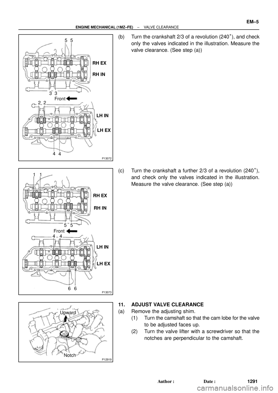
(b) Turn the crankshaft 2/3 of a revolution (240°), and check
only the valves indicated in the illustration. Measure the
valve clearance. (See step (a))
(c) Turn the crankshaft a further 2/3 of a revolution (240°),
and check only the valves indicated in the illustration.
Measure the valve clearance. (See step (a))
11. ADJUST VALVE CLEARANCE
(a) Remove the adjusting shim.
(1) Turn the camshaft so that the cam lobe for the valve
to be adjusted faces up.
(2) Turn the valve lifter with a screwdriver so that the
notches are perpendicular to the camshaft.
Page 3512 of 4770

SST (B) SST (B)
SST (A)
P12920
SST (B)
Magnetic Finger
EM0494
EM±6
± ENGINE MECHANICAL (1MZ±FE)VALVE CLEARANCE
1292 Author�: Date�:
(3) Using SS")
Z09456
Front of No.1 and No.2 Cylinder
OthersSST (A)
SST (B) SST (B)
SST (A)
P12920
SST (B)
Magnetic Finger
EM0494
EM±6
± ENGINE MECHANICAL (1MZ±FE)VALVE CLEARANCE
1292 Author�: Date�:
(3) Using SST (A), press down the valve lifter and place
SST (B) between the camshaft and valve lifter. Re-
move SST (A).
SST 09248±55040 (09248±05410, 09248±05420)
HINT:
�Apply SST (B) at a slight angle on the side marked with
º9º or º7º, at the position shown in the illustration.
�When SST (B) is inserted too deeply, it will get pinched by
the shim. To prevent it from being stuck, insert it gently
from the intake side, at a slight angle.
�Using a small screwdriver and magnetic finger, remove
the adjusting shim.
(b) Determine the replacement adjusting shim size according
to these Formula or Charts:
(1) Using a micrometer, measure the thickness of the
removed shim.
(2) Calculate the thickness of a new shim so the valve
clearance comes within the specified value.
T .......... Thickness of used shim
A .......... Measured valve clearance
N .......... Thickness of new shim
Intake
N = T + (A ± 0.20 mm (0.008 in.))
Exhaust
N = T + (A ± 0.30 mm (0.012 in.))
(3) Select a new shim with a thickness as close as pos-
sible to the calculated values.
HINT:
Shims are available in 17 sizes in increments of 0.050 mm
(0.0020 in.), from 2.500 mm (0.0984 in.) to 3.300 mm (0.1299
in.).
Page 3520 of 4770
B06384
No.2 Timing Belt CoverTiming Belt
Gasket
Timing Belt Guide
No.2 Generator
Bracket RH Engine Mounting Bracket
Crankshaft
PulleyGasket
Engine Wire
Protector
RH Camshaft Timing Pulley
No.2 Idler Pulley
Crankshaft
Timing PulleyDust Boot
Timing Belt Plate Plate Washer
�
Timing Belt Tensioner
N´m (kgf´cm, ft´lbf)
: Specified torque
� Non±reusable part No.1 Timing Belt Cover
LH Camshaft
Timing Pulley
No.1 Idler Pulley
� Precoated part
* For use with SST
28 (290, 21)
215 (2,200, 159)
125 (1,300, 94)*88 (900, 65)43 (440, 32)
34 (350, 25)
27 (280, 20)
125 (1,300, 94)
EM±14
± ENGINE MECHANICAL (1MZ±FE)TIMING BELT
1300 Author�: Date�:
Page 3522 of 4770
P18820
A01800
Clamp
Clamp
P18814
P18808
A05052
EM±16
± ENGINE MECHANICAL (1MZ±FE)TIMING BELT
1302 Author�: Date�:
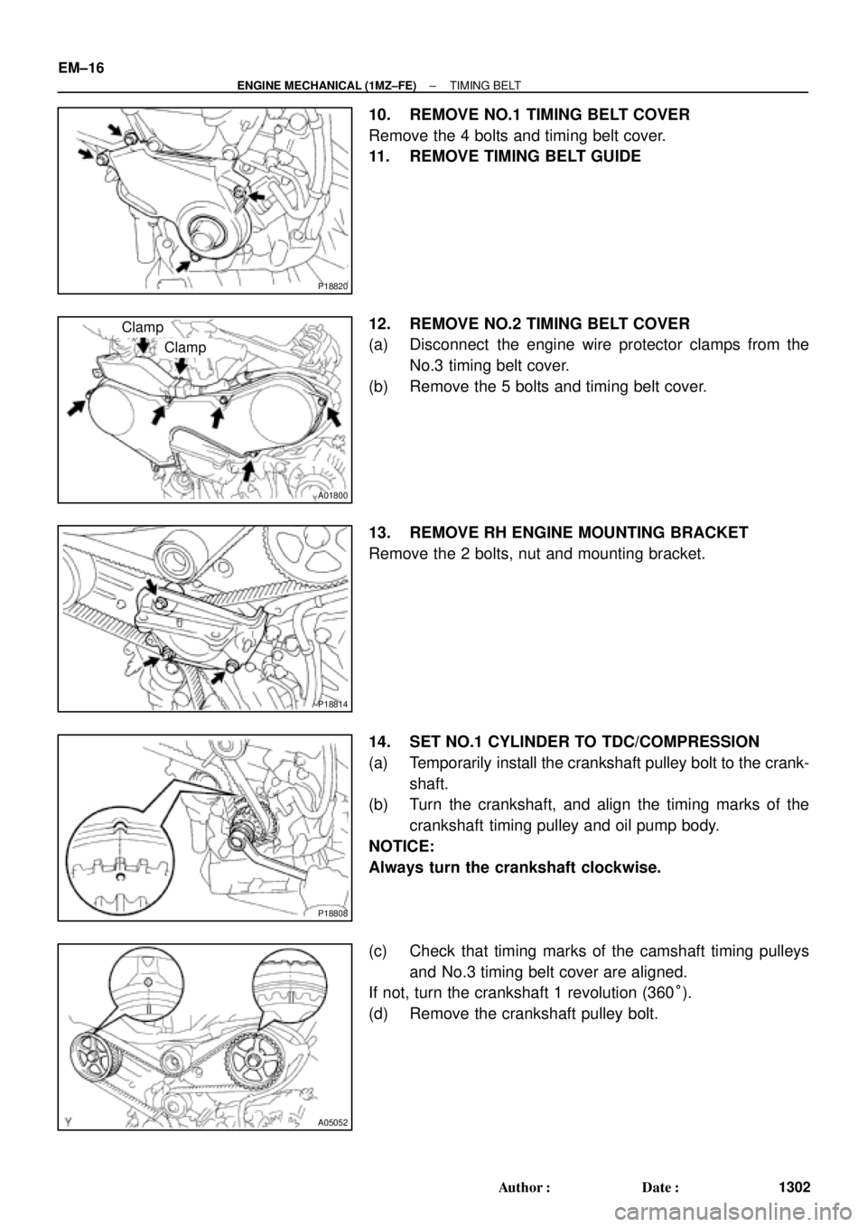
10. REMOVE NO.1 TIMING BELT COVER
Remove the 4 bolts and timing belt cover.
11. REMOVE TIMING BELT GUIDE
12. REMOVE NO.2 TIMING BELT COVER
(a) Disconnect the engine wire protector clamps from the
No.3 timing belt cover.
(b) Remove the 5 bolts and timing belt cover.
13. REMOVE RH ENGINE MOUNTING BRACKET
Remove the 2 bolts, nut and mounting bracket.
14. SET NO.1 CYLINDER TO TDC/COMPRESSION
(a) Temporarily install the crankshaft pulley bolt to the crank-
shaft.
(b) Turn the crankshaft, and align the timing marks of the
crankshaft timing pulley and oil pump body.
NOTICE:
Always turn the crankshaft clockwise.
(c) Check that timing marks of the camshaft timing pulleys
and No.3 timing belt cover are aligned.
If not, turn the crankshaft 1 revolution (360°).
(d) Remove the crankshaft pulley bolt.