Page 3540 of 4770
CYLINDER HEAD
1320 Author�: Date�:
10. REMOVE WATER OUTLET
(a) Disconnect the ECT sender gauge connector.
(b) Disconne")
P20049Gasket
A05077
Clamp
Clamp
Clamp
S04786
EM±34
± ENGINE MECHANICAL (1MZ±FE)CYLINDER HEAD
1320 Author�: Date�:
10. REMOVE WATER OUTLET
(a) Disconnect the ECT sender gauge connector.
(b) Disconnect the ECT sensor connector.
(c) Disconnect the ground strap (connector).
(d) Disconnect the radiator hose.
(e) Disconnect the engine coolant reservoir hose.
(f) Remove the 2 bolts, 2 nuts and 2 plate washers.
(g) Disconnect the water bypass hose, and remove the water
outlet.
(h) Remove the 2 gaskets.
11. REMOVE GENERATOR DRIVE BELT
(See page CH±6)
12. REMOVE PS PUMP (See page SR±21)
13. REMOVE IGNITION COILS
14. REMOVE SPARK PLUGS
15. REMOVE TIMING BELT (See page EM±15)
16. REMOVE CAMSHAFT TIMING PULLEYS
(See page EM±15)
17. REMOVE NO.2 IDLER PULLEY (See page EM±15)
18. REMOVE NO.3 TIMING BELT COVER
(a) Disconnect the 3 engine wire clamps from the timing belt
cover.
(b) Remove the 6 bolts and timing belt cover.
19. DISCONNECT ENGINE WIRE PROTECTOR FROM
REAR SIDE
Remove the 2 nuts, and disconnect the engine wire protector
from the RH cylinder head and water inlet.
Page 3542 of 4770
A06649
Manifold
Stay M/T and California A/T
Manifold
Stay
Except M/T and California A/T
P18769
A01522
Manifold
Stay California A/T
Manifold Stay
(Except M/T)Except California A/T
EM±36
± ENGINE MECHANICAL (1MZ±FE)CYLINDER HEAD
1322 Author�: Date�:
25. REMOVE RH EXHAUST MANIFOLD
(a) California A/T:
Disconnect the A/F sensor connector.
(b) Except California A/T:
Disconnect the heated oxygen sensor (bank 1 sensor 1)
connector.
(c) Remove the bolt, nut and exhaust manifold stay.
(d) Remove the 6 nuts, exhaust manifold and gasket.
26. REMOVE PS PUMP BRACKET
Remove the 3 bolts and pump bracket.
27. REMOVE LH EXHAUST MANIFOLD
(a) California A/T:
Disconnect the A/F sensor connector.
(b) Except California A/T:
Disconnect the heated oxygen sensor (bank 2 sensor 1)
connector.
(c) Except M/T:
Remove the bolt, nut and exhaust manifold stay.
(d) Remove the 6 nuts, exhaust manifold and gasket.
28. REMOVE CAMSHAFT POSITION SENSOR
Page 3543 of 4770
CYLINDER HEAD
EM±37
1323 Author�: Date�:
29. REMOVE OIL DIPSTICK AND GUIDE
(a) Re")
P12710
O±Ring
A01816
P12811Align Intake
P12871
Main Gear
Sub±Gear
Service Bolt Intake
± ENGINE MECHANICAL (1MZ±FE)CYLINDER HEAD
EM±37
1323 Author�: Date�:
29. REMOVE OIL DIPSTICK AND GUIDE
(a) Remove the bolt holding the dipstick guide to the LH cylin-
der head.
(b) Pull out the dipstick guide together with the dipstick from
the No.1 oil pan.
(c) Remove the O±ring from the dipstick guide.
30. REMOVE CYLINDER HEAD COVERS
Remove the 8 bolts, cylinder head cover and gasket. Remove
the 2 cylinder head covers.
31. REMOVE CAMSHAFTS OF RH CYLINDER HEAD
NOTICE:
Since the thrust clearance of the camshaft is small, the
camshaft must be held level while it is being removed. If the
camshaft is not kept level, the portion of the cylinder head
receiving the shaft thrust may crack or be damaged, caus-
ing the camshaft to seize or break. To avoid this, the follow-
ing steps should be carried out.
(a) Remove the intake camshaft.
(1) Align the timing marks (2 dot marks) of the camshaft
drive and driven gears by turning the camshaft with
a wrench.
(2) Secure the exhaust camshaft sub±gear to the main
gear with a service bolt.
Recommended service bolt:
Thread diameter6 mm
Thread pitch1.0 mm
Bolt length16 ± 20 mm (0.63 ± 0.79 in.)
Page 3544 of 4770
CYLINDER HEAD
1324 Author�: Date�:
HINT:
When removing the camshaft, mark ce")
P12780
Intake
7 85 6
3 41 2
9 10
P12888
7
85
6
3
41
2
9
10 Exhaust
P12917
Align Intake EM±38
± ENGINE MECHANICAL (1MZ±FE)CYLINDER HEAD
1324 Author�: Date�:
HINT:
When removing the camshaft, mark certain that the torsional
spring force of the sub±gear has been eliminated by the above
operation.
(3) Uniformly loosen and remove the 10 bearing cap
bolts, in several passes, in the sequence shown.
(4) Remove the 5 bearing caps and intake camshaft.
(b) Remove the exhaust camshaft.
(1) Uniformly loosen and remove the 10 bearing cap
bolts, in several passes, in the sequence shown.
(2) Remove the 5 bearing caps, oil seal and exhaust
camshaft.
32. REMOVE CAMSHAFTS OF LH CYLINDER HEAD
NOTICE:
Since the thrust clearance of the camshaft is small, the
camshaft must be held level while it is being removed. If the
camshaft is not kept level, the portion of the cylinder head
receiving the shaft thrust may crack or be damaged, caus-
ing the camshaft to seize or break. To avoid this, the follow-
ing steps should be carried out.
(a) Remove the intake camshaft.
(1) Align the timing marks (1 dot mark) of the camshaft
drive and driven gears by turning the camshaft with
a wrench.
Page 3545 of 4770
CYLINDER HEAD
EM±39
1325 Author�: Date�:
(2) Secur")
P12873Main Gear
Sub±GearService Bolt Intake
P12958
Intake
7
85
6
3
41
2
9
10
P12886
7
85 6
3 41 2
9 10 Exhaust
P12596
± ENGINE MECHANICAL (1MZ±FE)CYLINDER HEAD
EM±39
1325 Author�: Date�:
(2) Secure the exhaust camshaft sub±gear to the main
gear with a service bolt.
Recommended service bolt:
Thread diameter6 mm
Thread pitch1.0 mm
Bolt length16 ± 20 mm (0.63 ± 0.79 in.)
HINT:
When removing the camshaft, make sure that the torsional
spring force of the sub±gear has been eliminated by the above
operation.
(b) Uniformly loosen and remove the 10 bearing cap bolts, in
several passes, in the sequence shown.
(c) Remove the 5 bearing caps and intake camshaft.
(d) Remove the exhaust camshaft.
(1) Uniformly loosen and remove the 10 bearing cap
bolts, in several passes, in the sequence shown.
(2) Remove the 5 bearing caps, oil seal and exhaust
camshaft.
HINT:
�Arrange the camshafts in the correct order.
�Arrange the bearing caps in the correct order.
33. DISASSEMBLE EXHAUST CAMSHAFTS
(a) Mount the hexagonal wrench head portion of the cam-
shaft in a vise.
NOTICE:
Be careful not to damage the camshaft.
Page 3546 of 4770
P12797
SST
P12590
P12816
Recessed Head Bolt
8 mm Hexagon Wrench
Front EM±40
± ENGINE MECHANICAL (1MZ±FE)CYLINDER HEAD
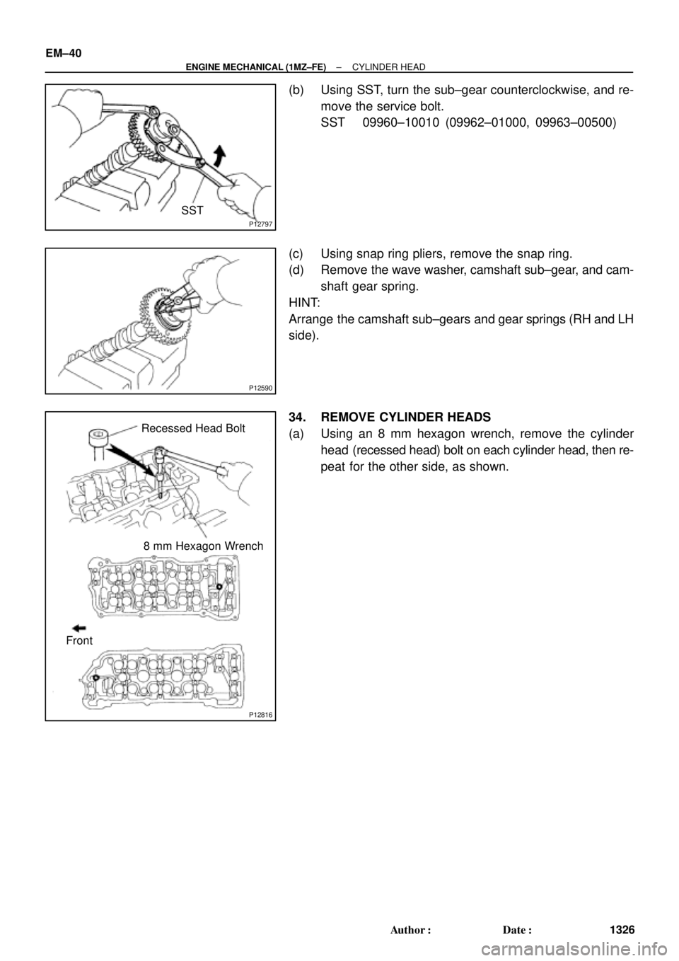
1326 Author�: Date�:
(b) Using SST, turn the sub±gear counterclockwise, and re-
move the service bolt.
SST 09960±10010 (09962±01000, 09963±00500)
(c) Using snap ring pliers, remove the snap ring.
(d) Remove the wave washer, camshaft sub±gear, and cam-
shaft gear spring.
HINT:
Arrange the camshaft sub±gears and gear springs (RH and LH
side).
34. REMOVE CYLINDER HEADS
(a) Using an 8 mm hexagon wrench, remove the cylinder
head (recessed head) bolt on each cylinder head, then re-
peat for the other side, as shown.
Page 3554 of 4770
CYLINDER HEAD
1334 Author�: Date�:
13. INSPECT CAMSHAFT FOR RUNOUT
(a) Place the camshaft on V±blocks.
(b) Using a dial indicator, mea")
EM1628
EM2011
EM2538
A05236
EM±48
± ENGINE MECHANICAL (1MZ±FE)CYLINDER HEAD
1334 Author�: Date�:
13. INSPECT CAMSHAFT FOR RUNOUT
(a) Place the camshaft on V±blocks.
(b) Using a dial indicator, measure the circle runout at the
center journal.
Maximum circle runout: 0.06 mm (0.0024 in.)
If the circle runout is greater than maximum, replace the cam-
shaft.
14. INSPECT CAM LOBES
Using a micrometer, measure the cam lobe height.
Standard cam lobe height:
Intake42.11 ± 42.21 mm (1.6579 ± 1.6618 in.)
Exhaust41.96 ± 42.06 mm (1.6520 ± 1.6559 in.)
Minimum cam lobe height:
Intake41.96 mm (1.6520 in.)
Exhaust41.81 mm (1.6461 in.)
If the cam lobe height is less than minimum, replace the cam-
shaft.
15. INSPECT CAMSHAFT JOURNALS
Using a micrometer, measure the journal diameter.
Journal diameter:
Intake26.949 ± 26.965 mm (1.0610 ± 1.0616 in.)
Exhaust26.959 ± 26.975 mm (1.0613 ± 1.0620 in.)
If the journal diameter is not as specified, check the oil clear-
ance.
16. INSPECT CAMSHAFT BEARINGS
Check that bearings for flaking and scoring.
If the bearings are damaged, replace the bearing caps and cyl-
inder head as a set.
Page 3555 of 4770
CYLINDER HEAD
EM±49
1335 Author�: Date�:
17. INSPECT CAMSHAFT JOURNAL OIL CLEARANCE
(a) Clean the bearing caps and camshaft journa")
P13009
Plastigage
P12892
P13004
P12891
± ENGINE MECHANICAL (1MZ±FE)CYLINDER HEAD
EM±49
1335 Author�: Date�:
17. INSPECT CAMSHAFT JOURNAL OIL CLEARANCE
(a) Clean the bearing caps and camshaft journals.
(b) Place the camshafts on the cylinder head.
(c) Lay a strip of Plastigage across each of the camshaft jour-
nal.
(d) Install the bearing caps. (See page EM±57)
Torque: 16 N´m (160 kgf´cm, 12 ft´lbf)
NOTICE:
Do not turn the camshaft.
(e) Remove the bearing caps.
(f) Measure the Plastigage at its widest point.
Standard oil clearance:
Intake0.035 ± 0.072 mm (0.0014 ± 0.0028 in.)
Exhaust0.025 ± 0.062 mm (0.0010 ± 0.0024 in.)
Maximum oil clearance:
Intake0.10 mm (0.0039 in.)
Exhaust0.09 mm (0.0035 in.)
If the oil clearance is greater than maximum, replace the cam-
shaft. If necessary, replace the bearing caps and cylinder head
as a set.
(g) Completely remove the Plastigage.
(h) Remove the camshafts.
18. INSPECT CAMSHAFT THRUST CLEARANCE
(a) Install the camshafts. (See page EM±57)
(b) Using a dial indicator, measure the thrust clearance while
moving the camshaft back and forth.
Standard thrust clearance:
0.040 ± 0.090 mm (0.0016 ± 0.0035 in.)
Maximum thrust clearance: 0.12 mm (0.0047 in.)
If the thrust clearance is greater than maximum, replace the
camshaft. If necessary, replace the bearing caps and cylinder
head as a set.
Except California A/T
EM±36
± ENGINE MECH")