Page 3444 of 4770
EM0YM±01
P03274
SST
Z02903
Intake Exhaust
Gray
Black
P03265
SST
P03276
EM±52
± ENGINE MECHANICAL (5S±FE)CYLINDER HEAD
1224 Author�: Date�:
REASSEMBLY
HINT:
�Thoroughly clean all parts to be assembled.
�Before installing the parts, apply new engine oil to all slid-
ing and rotating surfaces.
�Replace all gaskets and oil seals with new ones.
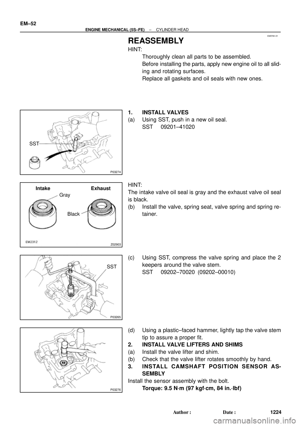
1. INSTALL VALVES
(a) Using SST, push in a new oil seal.
SST 09201±41020
HINT:
The intake valve oil seal is gray and the exhaust valve oil seal
is black.
(b) Install the valve, spring seat, valve spring and spring re-
tainer.
(c) Using SST, compress the valve spring and place the 2
keepers around the valve stem.
SST 09202±70020 (09202±00010)
(d) Using a plastic±faced hammer, lightly tap the valve stem
tip to assure a proper fit.
2. INSTALL VALVE LIFTERS AND SHIMS
(a) Install the valve lifter and shim.
(b) Check that the valve lifter rotates smoothly by hand.
3. INSTALL CAMSHAFT POSITION SENSOR AS-
SEMBLY
Install the sensor assembly with the bolt.
Torque: 9.5 N´m (97 kgf´cm, 84 in.´lbf)
Page 3445 of 4770
EM08D±04
A07355
Z02750
1
10 24 6 839
7 5
S01690
90°
Front
Painted
Mark90°
P03279
± ENGINE MECHANICAL (5S±FE)CYLINDER HEAD
EM±53
1225 Author�: Date�:
INSTALLATION
1. PLACE CYLINDER HEAD ON CYLINDER BLOCK
(a) Place a new cylinder head gasket on the cylinder block.
NOTICE:
Be careful of the installation direction.
(b) Place the cylinder head on the cylinder head gasket.
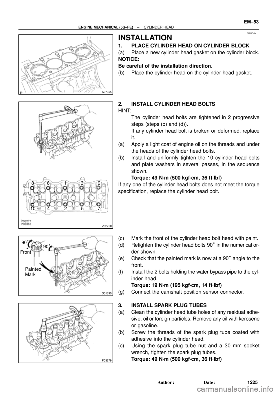
2. INSTALL CYLINDER HEAD BOLTS
HINT:
�The cylinder head bolts are tightened in 2 progressive
steps (steps (b) and (d)).
�If any cylinder head bolt is broken or deformed, replace
it.
(a) Apply a light coat of engine oil on the threads and under
the heads of the cylinder head bolts.
(b) Install and uniformly tighten the 10 cylinder head bolts
and plate washers in several passes, in the sequence
shown.
Torque: 49 N´m (500 kgf´cm, 36 ft´lbf)
If any one of the cylinder head bolts does not meet the torque
specification, replace the cylinder head bolt.
(c) Mark the front of the cylinder head bolt head with paint.
(d) Retighten the cylinder head bolts 90° in the numerical or-
der shown.
(e) Check that the painted mark is now at a 90° angle to the
front.
(f) Install the 2 bolts holding the water bypass pipe to the cyl-
inder head.
Torque: 19 N´m (195 kgf´cm, 14 ft´lbf)
(g) Connect the camshaft position sensor connector.
3. INSTALL SPARK PLUG TUBES
(a) Clean the cylinder head tube holes of any residual adhe-
sive, oil or foreign particles. Remove any oil with kerosene
or gasoline.
(b) Screw the threads of the spark plug tube coated with
adhesive into the cylinder head.
(c) Using the spark plug tube nut and a 30 mm socket
wrench, tighten the spark plug tubes.
Torque: 49 N´m (500 kgf´cm, 36 ft´lbf)
Page 3446 of 4770
P05617
Z02838
Wave Washer
Sub±Gear
Gear Spring
S01666
S01664
SST
Turn Sub±Gear
Service
BoltMain Gear EM±54
± ENGINE MECHANICAL (5S±FE)CYLINDER HEAD
1226 Author�: Date�:
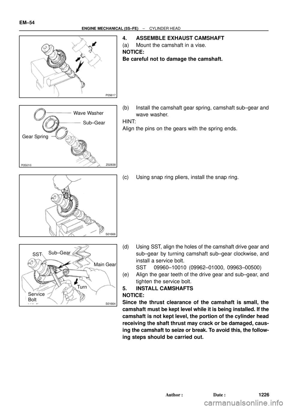
4. ASSEMBLE EXHAUST CAMSHAFT
(a) Mount the camshaft in a vise.
NOTICE:
Be careful not to damage the camshaft.
(b) Install the camshaft gear spring, camshaft sub±gear and
wave washer.
HINT:
Align the pins on the gears with the spring ends.
(c) Using snap ring pliers, install the snap ring.
(d) Using SST, align the holes of the camshaft drive gear and
sub±gear by turning camshaft sub±gear clockwise, and
install a service bolt.
SST 09960±10010 (09962±01000, 09963±00500)
(e) Align the gear teeth of the drive gear and sub±gear, and
tighten the service bolt.
5. INSTALL CAMSHAFTS
NOTICE:
Since the thrust clearance of the camshaft is small, the
camshaft must be kept level while it is being installed. If the
camshaft is not kept level, the portion of the cylinder head
receiving the shaft thrust may crack or be damaged, caus-
ing the camshaft to seize or break. To avoid this, the follow-
ing steps should be carried out.
Page 3447 of 4770
P03369
80 ±115°
Knock
Pin
EM3373
2 ± 3 mm
(0.08 ± 0.12 in.)
Seal
Packing
P03370
P03371
17
5
3
98
2
6
4
10
P03372
SST
± ENGINE MECHANICAL (5S±FE)CYLINDER HEAD
EM±55
1227 Author�: Date�:
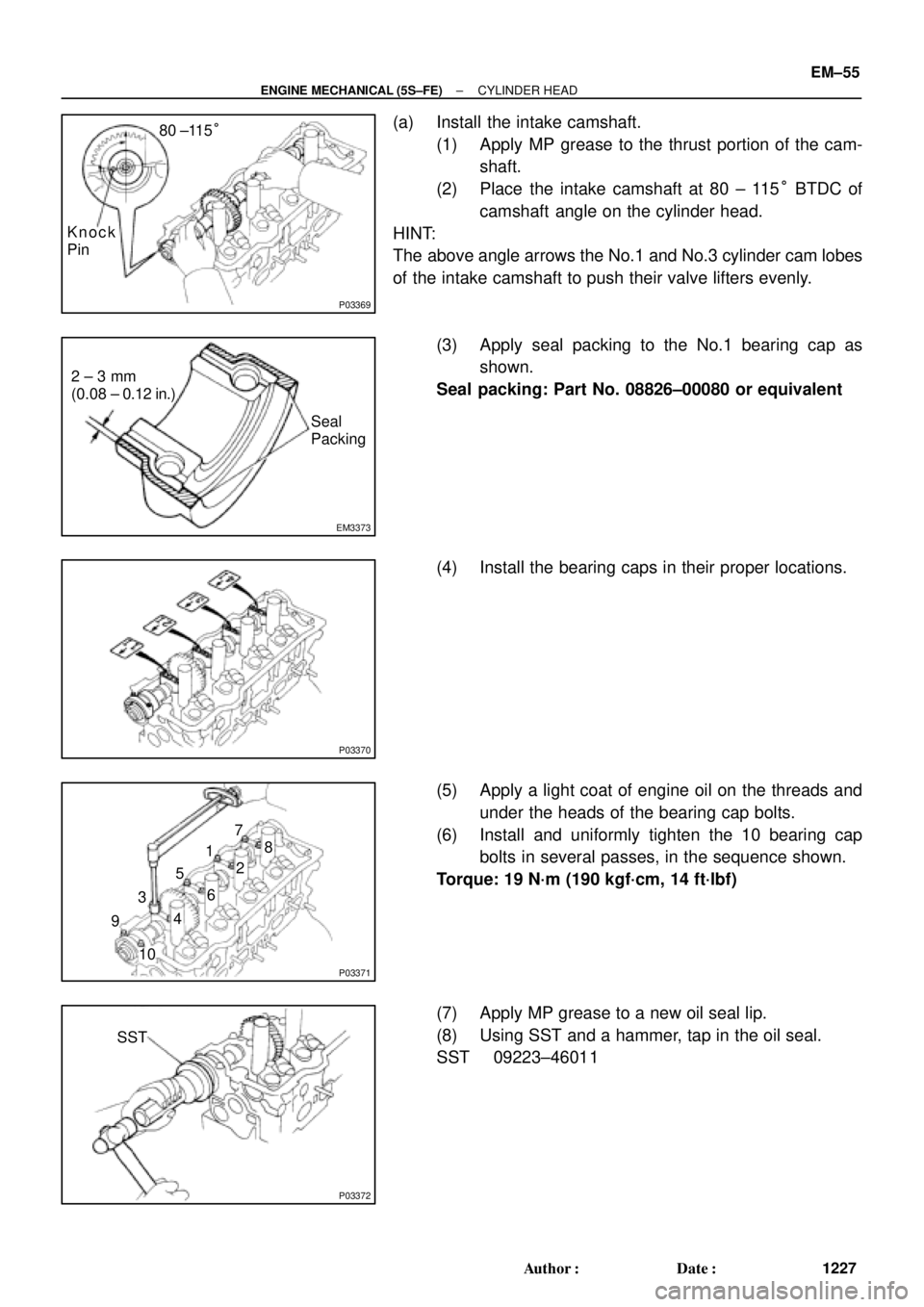
(a) Install the intake camshaft.
(1) Apply MP grease to the thrust portion of the cam-
shaft.
(2) Place the intake camshaft at 80 ± 115° BTDC of
camshaft angle on the cylinder head.
HINT:
The above angle arrows the No.1 and No.3 cylinder cam lobes
of the intake camshaft to push their valve lifters evenly.
(3) Apply seal packing to the No.1 bearing cap as
shown.
Seal packing: Part No. 08826±00080 or equivalent
(4) Install the bearing caps in their proper locations.
(5) Apply a light coat of engine oil on the threads and
under the heads of the bearing cap bolts.
(6) Install and uniformly tighten the 10 bearing cap
bolts in several passes, in the sequence shown.
Torque: 19 N´m (190 kgf´cm, 14 ft´lbf)
(7) Apply MP grease to a new oil seal lip.
(8) Using SST and a hammer, tap in the oil seal.
SST 09223±46011
Page 3448 of 4770
P03281
10 ± 45°
Knock
Pin
P03373
Assembly
Reference Mark
Timing
Mark
P03374
P03375
1 2
3 410
5 6
8
79 EM±56
± ENGINE MECHANICAL (5S±FE)CYLINDER HEAD
1228 Author�: Date�:
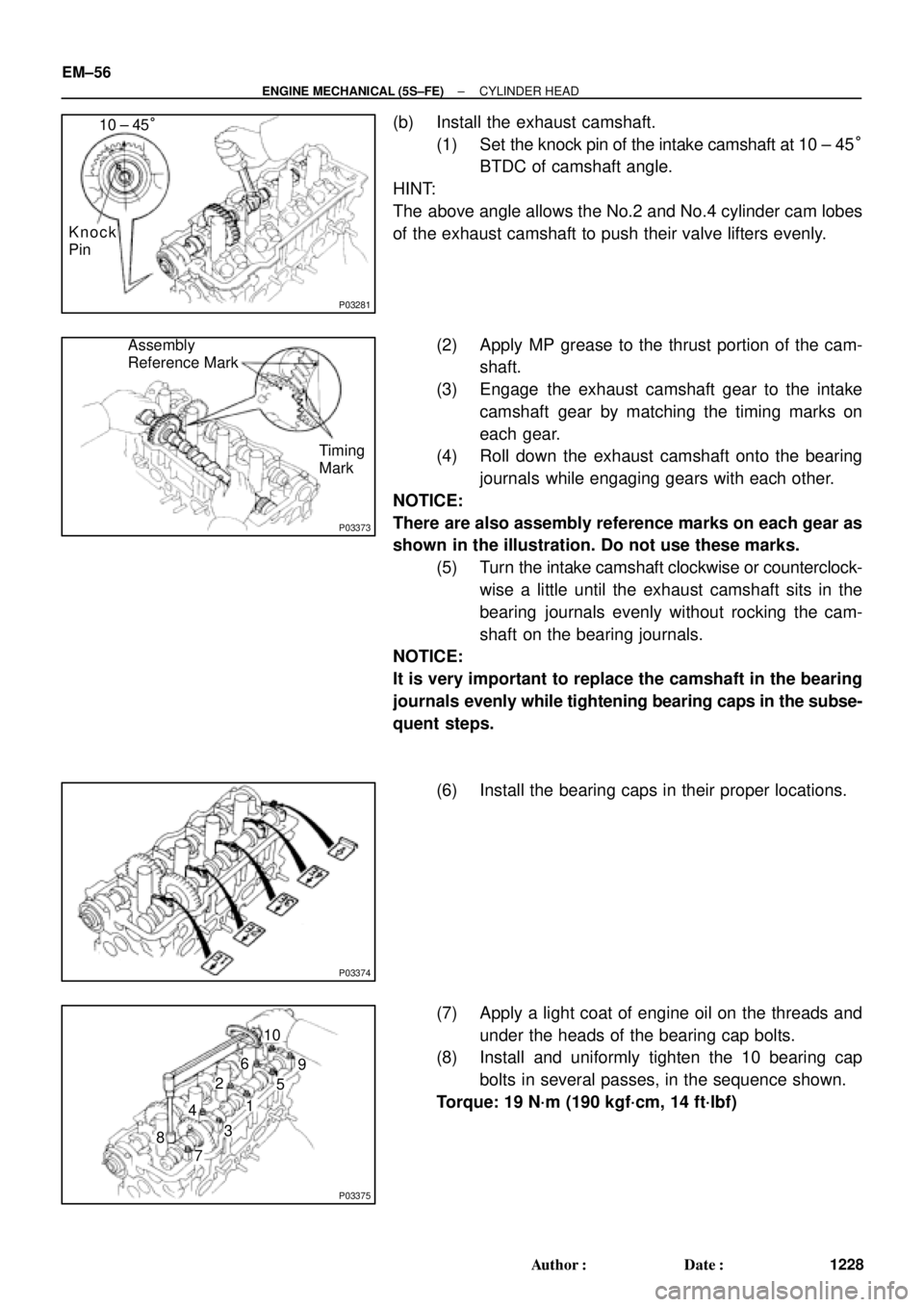
(b) Install the exhaust camshaft.
(1) Set the knock pin of the intake camshaft at 10 ± 45°
BTDC of camshaft angle.
HINT:
The above angle allows the No.2 and No.4 cylinder cam lobes
of the exhaust camshaft to push their valve lifters evenly.
(2) Apply MP grease to the thrust portion of the cam-
shaft.
(3) Engage the exhaust camshaft gear to the intake
camshaft gear by matching the timing marks on
each gear.
(4) Roll down the exhaust camshaft onto the bearing
journals while engaging gears with each other.
NOTICE:
There are also assembly reference marks on each gear as
shown in the illustration. Do not use these marks.
(5) Turn the intake camshaft clockwise or counterclock-
wise a little until the exhaust camshaft sits in the
bearing journals evenly without rocking the cam-
shaft on the bearing journals.
NOTICE:
It is very important to replace the camshaft in the bearing
journals evenly while tightening bearing caps in the subse-
quent steps.
(6) Install the bearing caps in their proper locations.
(7) Apply a light coat of engine oil on the threads and
under the heads of the bearing cap bolts.
(8) Install and uniformly tighten the 10 bearing cap
bolts in several passes, in the sequence shown.
Torque: 19 N´m (190 kgf´cm, 14 ft´lbf)
Page 3449 of 4770
P03445
Drive Gear
Sub±Gear Service
Bolt
EM7797
Seal Packing
P03282
P03283
: Seal Packing
S05932
Marking
15° 15°
± ENGINE MECHANICAL (5S±FE)CYLINDER HEAD
EM±57
1229 Author�: Date�:
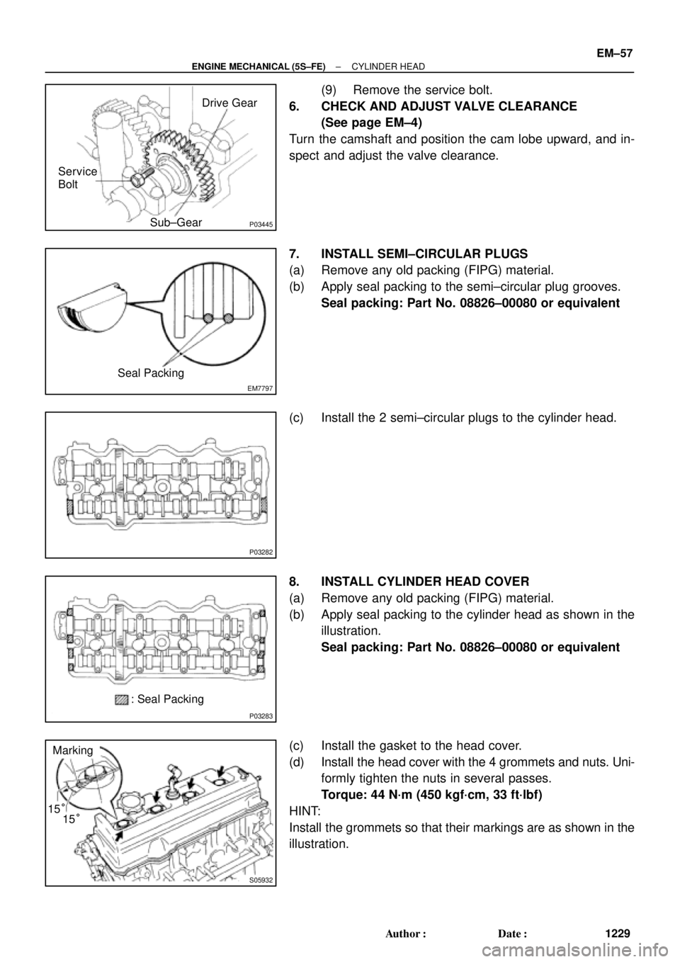
(9) Remove the service bolt.
6. CHECK AND ADJUST VALVE CLEARANCE
(See page EM±4)
Turn the camshaft and position the cam lobe upward, and in-
spect and adjust the valve clearance.
7. INSTALL SEMI±CIRCULAR PLUGS
(a) Remove any old packing (FIPG) material.
(b) Apply seal packing to the semi±circular plug grooves.
Seal packing: Part No. 08826±00080 or equivalent
(c) Install the 2 semi±circular plugs to the cylinder head.
8. INSTALL CYLINDER HEAD COVER
(a) Remove any old packing (FIPG) material.
(b) Apply seal packing to the cylinder head as shown in the
illustration.
Seal packing: Part No. 08826±00080 or equivalent
(c) Install the gasket to the head cover.
(d) Install the head cover with the 4 grommets and nuts. Uni-
formly tighten the nuts in several passes.
Torque: 44 N´m (450 kgf´cm, 33 ft´lbf)
HINT:
Install the grommets so that their markings are as shown in the
illustration.
Page 3450 of 4770
P13638
Adhesive
S05962
Z09141
California
Except California New O±RingNew Insulator
New GrommetNew O±Ring
New GrommetNew
O±Ring EM±58
± ENGINE MECHANICAL (5S±FE)CYLINDER HEAD
1230 Author�: Date�:
9. INSTALL OIL PRESSURE SWITCH
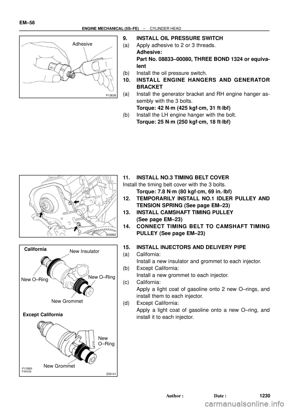
(a) Apply adhesive to 2 or 3 threads.
Adhesive:
Part No. 08833±00080, THREE BOND 1324 or equiva-
lent
(b) Install the oil pressure switch.
10. INSTALL ENGINE HANGERS AND GENERATOR
BRACKET
(a) Install the generator bracket and RH engine hanger as-
sembly with the 3 bolts.
Torque: 42 N´m (425 kgf´cm, 31 ft´lbf)
(b) Install the LH engine hanger with the bolt.
Torque: 25 N´m (250 kgf´cm, 18 ft´lbf)
11. INSTALL NO.3 TIMING BELT COVER
Install the timing belt cover with the 3 bolts.
Torque: 7.8 N´m (80 kgf´cm, 69 in.´lbf)
12. TEMPORARILY INSTALL NO.1 IDLER PULLEY AND
TENSION SPRING (See page EM±23)
13. INSTALL CAMSHAFT TIMING PULLEY
(See page EM±23)
14. CONNECT TIMING BELT TO CAMSHAFT TIMING
PULLEY (See page EM±23)
15. INSTALL INJECTORS AND DELIVERY PIPE
(a) California:
Install a new insulator and grommet to each injector.
(b) Except California:
Install a new grommet to each injector.
(c) California:
Apply a light coat of gasoline onto 2 new O±rings, and
install them to each injector.
(d) Except California:
Apply a light coat of gasoline onto a new O±ring, and
install it to each injector.
Page 3474 of 4770
EM08H±03
A07366
No.2 Timing Belt
Cover
No.1 Timing Belt
Cover
Crankshaft
Pulley
No.2 Idler PulleyTension Spring* Gasket
Timing Belt Guide Timing Belt
High±Tension Cord
Spark Plug
N´m (kgf´cm, ft´lbf)Wire
ClampGenerator
Wire Clamp
Crankshaft Timing Pulley
Camshaft Timing Pulley
No.1 Idler PulleyWire ClampWire Clamp
108 (1,100, 80)
54 (550, 40)
42 (425, 31)
18 (180, 13)
42 (425, 31)
: Specified torque* Gasket
* Replace only if damaged
EM±82
± ENGINE MECHANICAL (5S±FE)CYLINDER BLOCK
1254 Author�: Date�:
CYLINDER BLOCK
COMPONENTS