Page 2633 of 4770

± DIAGNOSTICSENGINE (1MZ±FE)
DI±213
448 Author�: Date�:
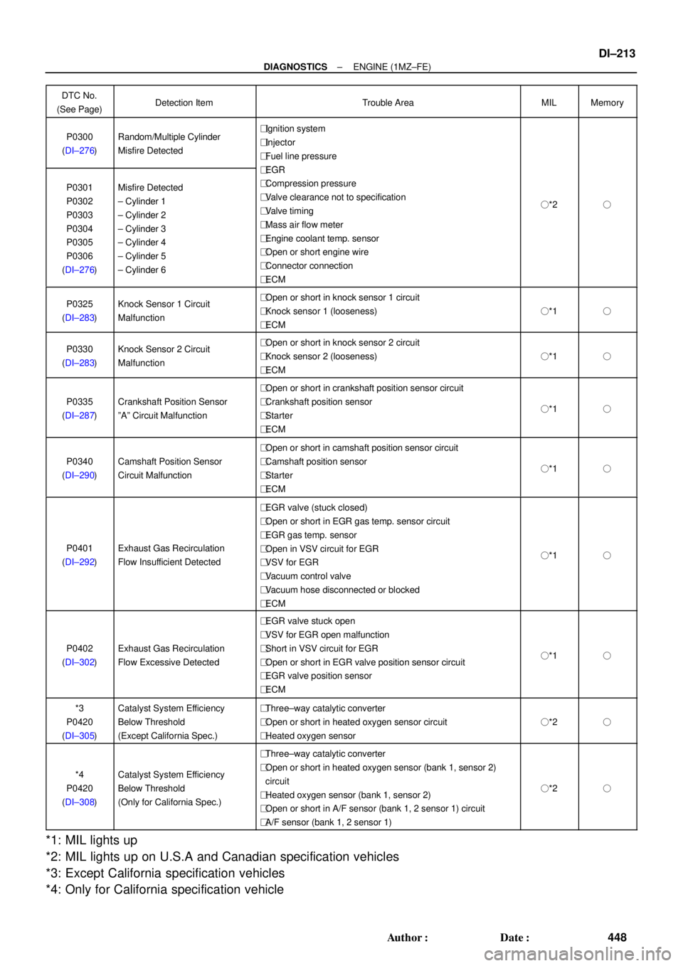
DTC No.
(See Page)Detection ItemTrouble AreaMILMemory
P0300
(DI±276)Random/Multiple Cylinder
Misfire Detected�Ignition system
�Injector
�Fuel line pressure
EGR
P0301
P0302
P0303
P0304
P0305
P0306
(DI±276)Misfire Detected
± Cylinder 1
± Cylinder 2
± Cylinder 3
± Cylinder 4
± Cylinder 5
± Cylinder 6
�EGR
�Compression pressure
�Valve clearance not to specification
�Valve timing
�Mass air flow meter
�Engine coolant temp. sensor
�Open or short engine wire
�Connector connection
�ECM
�*2�
P0325
(DI±283)Knock Sensor 1 Circuit
Malfunction�Open or short in knock sensor 1 circuit
�Knock sensor 1 (looseness)
�ECM
�*1�
P0330
(DI±283)Knock Sensor 2 Circuit
Malfunction�Open or short in knock sensor 2 circuit
�Knock sensor 2 (looseness)
�ECM
�*1�
P0335
(DI±287)Crankshaft Position Sensor
ºAº Circuit Malfunction
�Open or short in crankshaft position sensor circuit
�Crankshaft position sensor
�Starter
�ECM
�*1�
P0340
(DI±290)Camshaft Position Sensor
Circuit Malfunction
�Open or short in camshaft position sensor circuit
�Camshaft position sensor
�Starter
�ECM
�*1�
P0401
(DI±292)Exhaust Gas Recirculation
Flow Insufficient Detected
�EGR valve (stuck closed)
�Open or short in EGR gas temp. sensor circuit
�EGR gas temp. sensor
�Open in VSV circuit for EGR
�VSV for EGR
�Vacuum control valve
�Vacuum hose disconnected or blocked
�ECM
�*1�
P0402
(DI±302)Exhaust Gas Recirculation
Flow Excessive Detected
�EGR valve stuck open
�VSV for EGR open malfunction
�Short in VSV circuit for EGR
�Open or short in EGR valve position sensor circuit
�EGR valve position sensor
�ECM
�*1�
*3
P0420
(DI±305)Catalyst System Efficiency
Below Threshold
(Except California Spec.)�Three±way catalytic converter
�Open or short in heated oxygen sensor circuit
�Heated oxygen sensor
�*2�
*4
P0420
(DI±308)Catalyst System Efficiency
Below Threshold
(Only for California Spec.)
�Three±way catalytic converter
�Open or short in heated oxygen sensor (bank 1, sensor 2)
circuit
�Heated oxygen sensor (bank 1, sensor 2)
�Open or short in A/F sensor (bank 1, 2 sensor 1) circuit
�A/F sensor (bank 1, 2 sensor 1)
�*2�
*1: MIL lights up
*2: MIL lights up on U.S.A and Canadian specification vehicles
*3: Except California specification vehicles
*4: Only for California specification vehicle
Page 2637 of 4770
DI07C±06
A07469
Engine Coolant
Temp. Sensor
Heated Oxygen Sensor
(Bank 1 Sensor 2) VSV for EVAP VSV for ACIS
Crankshaft Position
Sensor
Camshaft Position
Sensor
Heated Oxygen Sensor *1
(Bank 1 Sensor 1)
A/F Sensor*2
(Bank 1 Sensor 1)Park/Neutral Position Switch
Knock Sensor 1 Knock Sensor 2
EGR Gas Temp. Sensor InjectorDLC1ECMVSV for EGR
IAC ValveMass Air Flow MeterIgniter
*1 : Except California Specification vehicles
*2 : Only for California Specification vehiclesVapor Pressure
Sensor
DLC3
Heated Oxygen Sensor *1
(Bank 2 Sensor 1)
A/F Sensor*2
(Bank 2 Sensor 1)
Canister
EGR Valve
Position Sensor
± DIAGNOSTICSENGINE (1MZ±FE)
DI±217
452 Author�: Date�:
PARTS LOCATION
Page 2696 of 4770

DI±276
± DIAGNOSTICSENGINE (1MZ±FE)
511 Author�: Date�:
DTC P0300 Random/Multiple Cylinder Misfire Detected
DTC P0301 Cylinder 1 Misfire Detected
DTC P0302 Cylinder 2 Misfire Detected
DTC P0303 Cylinder 3 Misfire Detected
DTC P0304 Cylinder 4 Misfire Detected
DTC P0305 Cylinder 5 Misfire Detected
DTC P0306 Cylinder 6 Misfire Detected
CIRCUIT DESCRIPTION
Misfire: The ECM uses the crankshaft position sensor and camshaft position sensor to monitor changes in
the crankshaft rotation for each cylinder.
The ECM counts the number of times the engine speed change rate indicates that misfire has occurred.
When the misfire rate equals or exceeds the count indicating that the engine condition has deteriorated, the
MIL lights up.
If the misfire rate is high enough and the driving conditions will cause catalyst overheating, the MIL blinks
when misfiring occurs.
DTC No.DTC Detecting ConditionTrouble Area
P0300Misfiring of random cylinders is detected during any
particular 200 or 1,000 revolutions�Ignition system
�Injector
�Fuel line pressure
P0301
P0302
P0303For any particular 200 revolutions for engine, misfiring is de-
tected which can cause catalyst overheating
(This causes MIL to blink)
�EGR
�Compression pressure
�Valve clearance not to specification
�Valve timing
�Mass air flow meterP0303
P0304
P0305
P0306For any particular 1,000 revolutions of engine, misfiring is de-
tected which causes a deterioration in emission
(2 trip detection logic)
�Mass air flow meter
�Engine coolant temp. sensor
�Open or short in engine wire
�Connector connection
�ECM
DI07S±07
Page 2707 of 4770

P25474
Camshaft Position Sensor
1
2
1
2B±W
B±RL
BR LECM
G22+
NE+
NE±
E2
E10
E10E11
2410
Crankshaft Position SensorB±R16
± DIAGNOSTICSENGINE (1MZ±FE)
DI±287
522 Author�: Date�:
DTC P0335 Crankshaft Position Sensor ºAº Circuit
Malfunction
CIRCUIT DESCRIPTION
Crankshaft position sensor (NE signal) consists of a signal plate and pickup coil.
The NE signal plate has 34 teeth and is mounted on the crankshaft. The NE signal sensor generates 34
signals for every engine revolution. The ECM detects the standard crankshaft angle based on the G22 sig-
nals, and the actual crankshaft angle and the engine speed by the NE signals.
DTC No.DTC Detecting ConditionTrouble Area
P0335
No crankshaft position sensor signal to ECM during cranking
(2 trip detection logic)�Open or short in crankshaft position sensor circuit
�Crankshaft position sensor
P0335No crankshaft position sensor signal to ECM with engine
speed 600 rpm or more (2 trip detection logic)
�Crankshaft osition sensor
�Starter
�ECM
WIRING DIAGRAM
INSPECTION PROCEDURE
HINT:
�Perform troubleshooting of DTC P0335 first. If no trouble is found, troubleshoot the following mechani-
cal systems.
�Read freeze frame data using TOYOTA hand±held tester or OBD II scan tool. because freeze frame
records the engine conditions when the malfunction is detected, when troubleshooting it is useful for
determining whether the vehicle was running or stopped, the engine warmed up or not, the air±fuel
ratio lean or rich, etc. at the time of the malfunction.
DI07U±06
Page 2710 of 4770

DI±290
± DIAGNOSTICSENGINE (1MZ±FE)
525 Author�: Date�:
DTC P0340 Camshaft Position Sensor Circuit
Malfunction
CIRCUIT DESCRIPTION
Camshaft position sensor (G22 signal) consist of a signal plate and pickup coil.
The G22 signal plate has one tooth, on its outer circumference and is mounted on the left bank camshafts.
When the camshafts rotate, the protrusion on the signal plate and the air gap on the pickup coil change,
causing fluctuations in the magnetic field and generating an electromotive force in the pickup coil.
The NE signal plate has 34 teeth and is mounted on the crankshaft. The NE signal sensor generates 34
signals for every engine revolution. The ECM detects the standard crankshaft angle based on the G22 signal
and the actual crankshaft angle and the engine speed by the NE signals.
DTC No.DTC Detecting ConditionTrouble Area
P0340
No camshaft position sensor signal to ECM during cranking
(2 trip detection logic)�Open or short in camshaft position sensor circuit
�Camshaft position sensor
P0340No camshaft position sensor signal to ECM with engine speed
600 rpm or more
�Camshaft osition sensor
�Starter
�ECM
WIRING DIAGRAM
Refer to DTC P0335 (Crankshaft Position Sensor ºAº Circuit Malfunction) on page DI±287 .
INSPECTION PROCEDURE
HINT:
Read freeze frame data using TOYOTA hand±held tester or OBD II scan tool. Because freeze frame records
the engine conditions when the malfunction is detected, when troubleshooting it is useful for determining
whether the vehicle was running or stopped, the engine warmed up or not, the air±fuel ratio lean or rich, etc.
at the time of the malfunction.
1 Check resistance of camshaft position sensor (See page IG±1).
Reference INSPECTION USING OSCILLOSCOPE
Refer to DTC P0335 on page DI±287.
NG Replace camshaft position sensor.
OK
DI07V±06
Page 2711 of 4770
± DIAGNOSTICSENGINE (1MZ±FE)
DI±291
526 Author�: Date�:
2 Check for open and short in harness and connector between ECM and camshaft
position sensor (See page IN±31).
NG Repair or replace harness or connector.
OK
3 Inspect sensor installation and tooth of left bank camshaft timing pulley.
NG Tighten the sensor.
Replace left bank camshaft timing pulley.
OK
Check and replace ECM (See page IN±31).
Page 2771 of 4770

S00251
From BatteryIgnition Coil
Spark Plug
IGC1
IGC2
IGC3
GND TA C IGT1
IGT2
IGT3
IGF
To Tachometer ECM G
NE
Camshaft
Position
Sensor
Crankshaft
Position
Sensor
Various
SensorNo.2 Cylinder
No.1 Cylinder
No.4 Cylinder
No.3 Cylinder
No.6 Cylinder
No.5 Cylinder
± DIAGNOSTICSENGINE (1MZ±FE)
DI±351
586 Author�: Date�:
DTC P1300 Igniter Circuit Malfunction
CIRCUIT DESCRIPTION
A DIS (Direct Ignition System) has been adopted. The DIS improves the ignition timing accuracy, reduces
high±voltage loss, and enhances the overall reliability of the ignition system by eliminating the distributor.
The DIS is a 2±cylinder simultaneous ignition system which ignites 2 cylinders simultaneously with one igni-
tion coil. In the 2±cylinder simultaneous ignition system, each of the 2 spark plugs is connected to the end
of the secondary winding. High voltage generated in the secondary winding is applied directly to the spark
plugs. The sparks of the 2 spark plugs pass simultaneously from the center electrode to the ground elec-
trode.
The ECM determines ignition timing and outputs the ignition signals (IGT) for each cylinder. Based on IGT
signals, the igniter controls the primary ignition signals (IGC) for all ignition coils. At the same time, the igniter
also sends an ignition confirmation signal (IGF) as a fail±safe measure to the ECM.
DTC No.DTC Detecting ConditionTrouble Area
P1300
Condition (a) is repeated 3 times consecutively during 6
consecutively IGT signals while engine is running
(a) IGF signal is not input to ECM for 2 or more ignitions�Open or short in IGF or IGT circuit from igniter to ECM
�Igniter
�ECM
DI084±06
Page 3396 of 4770

EM07Z±03
S05289
(c)
(d) (e)
S05590
Turn
P03443
1 11 122
33 EM±4
± ENGINE MECHANICAL (5S±FE)VALVE CLEARANCE
1176 Author�: Date�:
VALVE CLEARANCE
INSPECTION
HINT:
Inspect and adjust the valve clearance when the engine is cold.
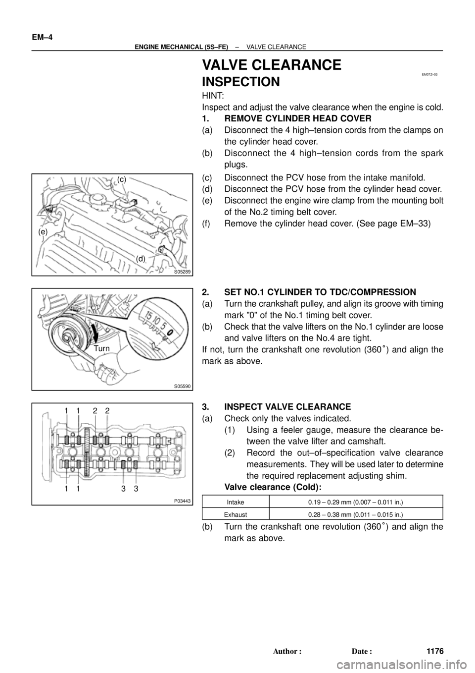
1. REMOVE CYLINDER HEAD COVER
(a) Disconnect the 4 high±tension cords from the clamps on
the cylinder head cover.
(b) Disconnect the 4 high±tension cords from the spark
plugs.
(c) Disconnect the PCV hose from the intake manifold.
(d) Disconnect the PCV hose from the cylinder head cover.
(e) Disconnect the engine wire clamp from the mounting bolt
of the No.2 timing belt cover.
(f) Remove the cylinder head cover. (See page EM±33)
2. SET NO.1 CYLINDER TO TDC/COMPRESSION
(a) Turn the crankshaft pulley, and align its groove with timing
mark º0º of the No.1 timing belt cover.
(b) Check that the valve lifters on the No.1 cylinder are loose
and valve lifters on the No.4 are tight.
If not, turn the crankshaft one revolution (360°) and align the
mark as above.
3. INSPECT VALVE CLEARANCE
(a) Check only the valves indicated.
(1) Using a feeler gauge, measure the clearance be-
tween the valve lifter and camshaft.
(2) Record the out±of±specification valve clearance
measurements. They will be used later to determine
the required replacement adjusting shim.
Valve clearance (Cold):
Intake0.19 ± 0.29 mm (0.007 ± 0.011 in.)
Exhaust0.28 ± 0.38 mm (0.011 ± 0.015 in.)
(b) Turn the crankshaft one revolution (360°) and align the
mark as above.