Page 3397 of 4770

SST (B)
P13926
Magnetic
Finger
EM0494
± ENGINE MECHANICAL (5S±FE)VALVE CLEARANCE
EM±5
1177 Author�: Dat")
P03442
2 233 44
44
P13927
Upward
Cam Lobe
Notch
Spark Plug Side
P13988Spark Plug Side SST (A)
SST (B)
P13926
Magnetic
Finger
EM0494
± ENGINE MECHANICAL (5S±FE)VALVE CLEARANCE
EM±5
1177 Author�: Date�:
(c) Check only the valves indicated as shown. Measure the
valve clearance. (See step (a))
4. ADJUST VALVE CLEARANCE
(a) Remove the adjusting shim.
(1) Turn the crankshaft so that the cam lobe of the cam-
shaft on the adjusting valve points upward.
(2) Position the notch of the valve lifter facing the spark
plug side.
(3) Using SST (A), press down the valve lifter and place
SST (B) between the camshaft and valve lifter. Re-
move SST (A).
SST 09248±55040 (09248±05410, 09248±05420)
HINT:
Apply SST (B) at slight angle on the side marked with º9º, at the
position shown in the illustration.
(4) Remove the adjusting shim with a small screwdriver
and magnetic finger.
(b) Determine the replacement adjusting shim size by follow-
ing the Formula or Charts:
(1) Using a micrometer, measure the thickness of the
removed shim.
(2) Calculate the thickness of a new shim so that the
valve clearance comes within specified value.
T ........... Thickness of removed shim
A ........... Measured valve clearance
N ........... Thickness of new shim
Intake: N = T + (A ± 0.24 mm (0.009 in.))
Page 3408 of 4770
S05937
No.2 Timing Belt
Cover
No.1 Timing Belt
Cover
Tension Spring Crankshaft
Pulley
Camshaft Timing Pulley
No.1 Idler Pulley
No.2 Idler Pulley
Oil Pump Pulley
Crankshaft Timing Pulley Wire ClampWire ClampWire ClampSpark Plug High±Tension CordTiming Belt Guide Timing Belt
*
1 Gasket Wire
ClampGenerator Wire
Generator Connector
Generator
Wire
Clamp
N´m (kgf´cm, ft´lbf)
*
2 For use with SST
42 (425, 31)
42 (425, 31)
24 (245, 18)18 (180, 13) 108 (1,100, 80)
54 (550, 40)
*
2
37 (380, 27)
: Specified torque*
1 Gasket
*
1
Replace only if damaged EM±16
± ENGINE MECHANICAL (5S±FE)TIMING BELT
1188 Author�: Date�:
Page 3410 of 4770
TIMING BELT
1190 Author�: Date�:
10. SET NO.1 CYLINDER TO TDC/COMPRESSION
(a) Turn the crankshaft pulley, an")
S05587
Turn
S05580
A02585
S05583
Pry
Move
S05593
SSTSST EM±18
± ENGINE MECHANICAL (5S±FE)TIMING BELT
1190 Author�: Date�:
10. SET NO.1 CYLINDER TO TDC/COMPRESSION
(a) Turn the crankshaft pulley, and align its groove with timing
mark º0º of the No.1 timing belt cover.
(b) Check that the hole of the camshaft timing pulley is
aligned with the timing mark of the bearing cap.
If not, turn the crankshaft 1 revolution (360°).
11. REMOVE TIMING BELT FROM CAMSHAFT TIMING
PULLEY
HINT:
When re±using timing belt:
Affix the matching marks on the timing belt and the camshaft
timing pulley, and the timing belt and the No. 1 timing belt cover.
(a) Loosen the mounting bolt of the No.1 idler pulley, and shift
the pulley toward the left as far as it will go, and temporari-
ly tighten it.
(b) Remove the timing belt from the camshaft timing pulley.
12. REMOVE CAMSHAFT TIMING PULLEY
(a) Using SST, loosen the pulley bolt.
SST 09249±63010, 09960±10010 (09962±01000,
09963±01000)
(b) Remove the bolt and timing pulley.
Page 3414 of 4770
TIMING BELT
1194 Author�: Date�:
INSPECTION
1. INSPECT TIMING BELT
NOTICE:
�Do not bend, twist or turn the t")
EM085±03
EM3336
No!
S01519
Turn
Seal
P15243Free Length EM±22
± ENGINE MECHANICAL (5S±FE)TIMING BELT
1194 Author�: Date�:
INSPECTION
1. INSPECT TIMING BELT
NOTICE:
�Do not bend, twist or turn the timing belt inside out.
�Do not allow the timing belt to come into contact with
oil, water or steam.
�Do not utilize timing belt tension when installing or re-
moving the mounting bolt of the camshaft timing
pulley.
If there are any defects as shown in the illustration, check these
points:
(a) Premature parting
�Check for proper installation.
�Check the timing cover gasket for damage and
proper installation.
(b) If the belt teeth are cracked or damaged, check to see if
either camshaft or water pump is locked.
(c) If there is noticeable wear or cracks on the belt face,
check to see if there are nicks on the side of the idler
pulley lock.
(d) If there is wear or damage on only one side of the belt,
check the belt guide and the alignment of each pulley.
(e) If there is noticeable wear on the belt teeth, check the tim-
ing cover for damage and check gasket has been
installed correctly and for foreign material on the pulley
teeth.
If necessary, replace the timing belt.
2. INSPECT IDLER PULLEYS
(a) Visually check the seal portion of the idler pulley for oil
leakage.
If leakage is found, replace the idler pulley.
(b) Check that the idler pulley turns smoothly.
If necessary, replace the idler pulley.
3. INSPECT TENSION SPRING
(a) Measure the free length of tension spring.
Free length: 42.0 mm (1.654 in.)
If the free length is not as specified, replace the tension spring.
(b) Measure the tension of the tension spring at the specified
installed length.
Installed tension (at 50.5 mm (1.988 in.)):
32 ± 37 N (3.25 ± 3.75 kgf, 7.2 ± 8.3 lbf)
If the installed tension is not as specified, replace the tension
spring.
Page 3417 of 4770
TIMING BELT
EM±25
1197 Author�: Date�:
(b) Install the timing belt cover with the 4 bolts.
(c) Install the")
A02591
S05588
SSTSST
S05592
SST
SST
Fulcrum
Length
S05587
Turn
± ENGINE MECHANICAL (5S±FE)TIMING BELT
EM±25
1197 Author�: Date�:
(b) Install the timing belt cover with the 4 bolts.
(c) Install the clamp of the crankshaft position sensor wire to
the timing belt cover.
(d) Install the crankshaft position sensor wire to the clamp on
the timing belt cover.
8. INSTALL CRANKSHAFT PULLEY
(a) Align the pulley set key with the key groove of the pulley,
and slide on the pulley.
(b) Using SST (and bolt), install the pulley bolt.
SST 09213±54015 (91651±60855),09330±00021
Torque: 108 N´m (1,100 kgf´cm, 80 ft´lbf)
HINT:
Either of 2 types of pulley may be used, each with its own bolt
size, type A (91651±60855) and type B
(part No. 91121±40665).
9. INSTALL CAMSHAFT TIMING PULLEY
(a) Align the camshaft knock pin with the knock pin groove of
the pulley, and slide on the timing pulley.
(b) Using SST, install the pulley bolt.
SST 09249±63010, 09960±10010 (09962±01000,
09963±01000)
Torque:
54 N´m (550 kgf´cm, 40 ft´lbf)
37 N´m (380 kgf´cm, 27 ft´lbf) for use with SST
HINT:
Use a torque wrench with a fulcrum length of 340 mm (13.39
in.).
10. SET NO.1 CYLINDER TO TDC/COMPRESSION
(a) Turn the crankshaft pulley, and align its groove with timing
mark º0º of the No.1 timing belt cover.
Page 3418 of 4770
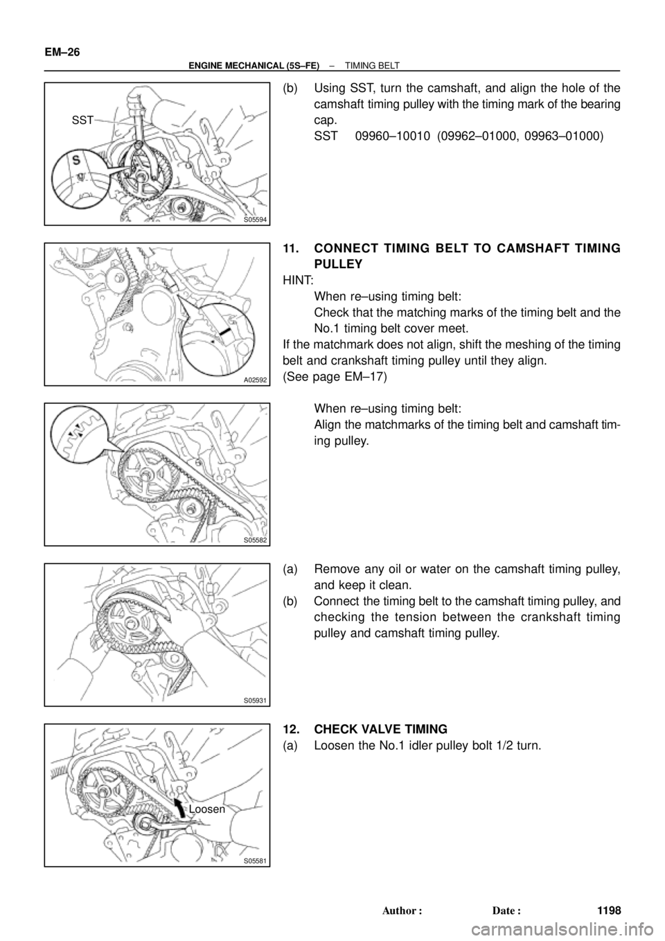
S05594
SST
A02592
S05582
S05931
S05581
Loosen EM±26
± ENGINE MECHANICAL (5S±FE)TIMING BELT
1198 Author�: Date�:
(b) Using SST, turn the camshaft, and align the hole of the
camshaft timing pulley with the timing mark of the bearing
cap.
SST 09960±10010 (09962±01000, 09963±01000)
11. CONNECT TIMING BELT TO CAMSHAFT TIMING
PULLEY
HINT:
�When re±using timing belt:
Check that the matching marks of the timing belt and the
No.1 timing belt cover meet.
If the matchmark does not align, shift the meshing of the timing
belt and crankshaft timing pulley until they align.
(See page EM±17)
�When re±using timing belt:
Align the matchmarks of the timing belt and camshaft tim-
ing pulley.
(a) Remove any oil or water on the camshaft timing pulley,
and keep it clean.
(b) Connect the timing belt to the camshaft timing pulley, and
checking the tension between the crankshaft timing
pulley and camshaft timing pulley.
12. CHECK VALVE TIMING
(a) Loosen the No.1 idler pulley bolt 1/2 turn.
Page 3424 of 4770

A07368
Spark Plug
Grommet
Cylinder Head Cover
Gasket
Camshaft Bearing Cap
� Camshaft Oil Seal
Camshaft Timing Pulley
Snap Ring
Wave Washer
Camshaft Position Sensor Connector
Camshaft Position Sensor Assembly
Wire Clamp
No. 3 Timing Belt Cover
No.2 Timing Belt Cover� Oil Seal
Valve Guide
Bushing
Cylinder
Head
Gasket Adjusting Shim
Valve Lifter
Keeper
Spring Retainer
Valve Spring
Spring Seat
Valve
LH Engine
Hanger
Semi±Circular
Plug
Oil Pressure
Switch
Camshaft Gear Spring
Camshaft Sub±Gear
Semi±Circular
Plug
Tension Spring
No.1 Idler Pulley
*
1
GasketTiming Belt
Cylinder Head Intake
CamshaftExhaust
Camshaft
Wire
Clamp
Wire
Clamp
Generator Bracket and
RH Engine Hanger
Assembly
N´m (kgf´cm, ft´lbf)
*
2 For use with SST
� Non±reusable part
18 (180, 13)
44 (450, 33)
19 (190, 14)
*
237 (380, 27)1st 49 (500, 36)
2nd Turn 90°
42 (425, 31)
x 10�
�
: Specified torque
See page EM±53
*1
Replace only if damaged
54 (550, 40)
EM±32
± ENGINE MECHANICAL (5S±FE)CYLINDER HEAD
1204 Author�: Date�:
Page 3428 of 4770
CYLINDER HEAD
1208 Author�: Date�:
(f) Remove the 6 bolts, 2 nuts, intake manifold and gasket.
15. California:
REMOVE AIR HOSE FOR AIR ASSIST S")
A07359
S06000
S05962
EM±36
± ENGINE MECHANICAL (5S±FE)CYLINDER HEAD
1208 Author�: Date�:
(f) Remove the 6 bolts, 2 nuts, intake manifold and gasket.
15. California:
REMOVE AIR HOSE FOR AIR ASSIST SYSTEM
Disconnect the air hose from the cylinder head port, and re-
move the air hose.
16. REMOVE DELIVERY PIPE AND INJECTORS
(a) Disconnect the 4 injector connectors.
(b) Remove the 2 bolts and delivery pipe together with the 4
injectors.
NOTICE:
Be careful not to drop the injectors when removing the de-
livery pipe.
(c) Remove the 4 insulators (except California) and 2
spacers from the cylinder head.
(d) Pull out the 4 injectors from the delivery pipe.
(e) California:
Remove the 2 O±rings, insulator and grommet from each
injector.
(f) Except California:
Remove the O±ring and grommet from each injector.
17. DISCONNECT TIMING BELT FROM CAMSHAFT TIM-
ING PULLEY (See page EM±17)
18. REMOVE CAMSHAFT TIMING PULLEY
(See page EM±17)
19. REMOVE NO.1 IDLER PULLEY AND TENSION
SPRING
Remove the bolt, pulley and tension spring.
20. REMOVE NO.3 TIMING BELT COVER
Remove the 3 bolts and timing and cover.