Page 3429 of 4770
CYLINDER HEAD
EM±37
1209 Author�: Date�:
NOTICE:
�Support the timing belt, so the meshing of the crank-
shaft timing pulley and")
A02593
S05933
P03355
10 ± 45°
Knock
Pin
± ENGINE MECHANICAL (5S±FE)CYLINDER HEAD
EM±37
1209 Author�: Date�:
NOTICE:
�Support the timing belt, so the meshing of the crank-
shaft timing pulley and timing belt does not shift.
�Be careful not to drop anything inside the timing belt
cover.
�Do not allow the belt to come into contact with oil, wa-
ter or dust.
21. REMOVE ENGINE HANGERS AND GENERATOR
BRACKET
(a) Remove the 3 bolts, the generator bracket and RH engine
hanger assembly.
(b) Remove the bolt and LH engine hanger.
22. REMOVE OIL PRESSURE SWITCH
23. REMOVE CYLINDER HEAD COVER
Remove the 4 nuts, grommets, head cover and gasket.
HINT:
Arrange the grommets in the correct order, so that they can be
reinstalled into their original positions. This minimizes any pos-
sibility of oil leakage due to reuse of the grommets in different
positions.
24. REMOVE CAMSHAFTS
NOTICE:
Since the thrust clearance of the camshaft is small, the
camshaft must be kept level while it is being removed. If the
camshaft is not kept level, the portion of the cylinder head
receiving the shaft thrust may crack or be damaged, caus-
ing the camshaft to seize or break. To avoid this, the follow-
ing steps should be carried out.
(a) Remove the exhaust camshaft.
(1) Set the knock pin of the intake camshaft at 10 ± 45°
BTDC of camshaft angle.
HINT:
The above angle allows No.2 and No.4 cylinder cam lobes of
the exhaust camshaft to push their valve lifters evenly.
Page 3430 of 4770
CYLINDER HEAD
1210 Author�: Date�:
(2) Secure the exhaust camshaft sub±gear to drive
gear w")
P03445
Drive Gear
Service
Bolt
Sub±Gear
P03356
P03241
3
26 54
1
P03357
EM±38
± ENGINE MECHANICAL (5S±FE)CYLINDER HEAD
1210 Author�: Date�:
(2) Secure the exhaust camshaft sub±gear to drive
gear with a service bolt.
Recommended service bolt:
Thread diameter6 mm
Thread pitch1.0 mm
Bolt length16 ± 20 mm (0.63 ± 0.79 in.)
HINT:
When removing the camshaft, make sure that the torsional
spring force of the sub±gear has been eliminated by the above
operation.
(3) Remove the 2 bolts and rear bearing cap.
(4) Uniformly loosen and remove the 6 bolts on the
No.1, No.2 and No.4 bearing caps in several
passes, in the sequence shown.
NOTICE:
Do not remove the No.3 bearing cap bolts at this stage.
(5) Remove the No.1, No.2 and No.4 bearing caps.
(6) Alternately loosen and remove the 2 bolts on the
No.3 bearing cap.
HINT:
�As the 2 No.3 bearing cap bolts are loosened, make sure
that the camshaft is lifted out straight and level.
�If the camshaft is not being lifted out straight and level, re-
tighten the 2 No.3 bearing cap bolts. Then reverse the or-
der of above steps from (6) to (1) and reset the knock pin
of the intake camshaft at 10 ± 45° BTDC, and repeat
steps from (2) to (6) once again.
NOTICE:
Do not pry on or attempt to force the camshaft with a tool
or other object.
(7) Remove the No.3 bearing cap and exhaust cam-
shaft.
Page 3431 of 4770
CYLINDER HEAD
EM±39
1211 Author�: Date�:
(b) Remove the intake camshaft.
(1) Set the knock pin of the intak")
P03358
8 0 ± 11 5°
Knock
Pin
P03359
P03360
1 2
3 45 6
P03361
± ENGINE MECHANICAL (5S±FE)CYLINDER HEAD
EM±39
1211 Author�: Date�:
(b) Remove the intake camshaft.
(1) Set the knock pin of the intake camshaft at 80 ±
11 5° BTDC of camshaft angle.
HINT:
The above angle allows the No.1 and No.3 cylinder cam lobes
of intake camshaft to push their valve lifters evenly.
(2) Remove the 2 bolts, front bearing cap and oil seal.
(3) Uniformly loosen and remove the 6 bolts on the
No.1, No.3 and No.4 bearing caps in several
passes, in the sequence shown.
NOTICE:
Do not remove the No.2 bearing cap bolts at this stage.
(4) Remove the No.1, No.3 and No.4 bearing caps.
(5) Alternately loosen and remove the 2 bolts on the
No.2 bearing cap.
HINT:
�As the 2 No.2 bearing cap bolts are loosened, make sure
that the camshaft is lifted out straight and level, after
breaking adhesion on the front bearing cap.
�If the camshaft is not being lifted out straight and level, re-
tighten the 2 No.2 bearing cap bolts. Reverse the order
of above steps from (5) to (1) and reset the knock pin of
the intake camshaft at 80 ± 115° BTDC, and repeat steps
from (2) to (5) once again.
NOTICE:
Do not pry on or attempt to force the camshaft with a tool
or other object.
(6) Remove the No.2 bearing cap and camshaft.
Page 3432 of 4770
CYLINDER HEAD
1212 Author�: Date�:
25. DISASSEMBLE EXHAUST CAMSHAFT
(a) Mount the camshaft")
P05613
S01665
SST
Service
Bolt
S01666
EM7558
6 10
192 8 3
74 5
S05971
Pry EM±40
± ENGINE MECHANICAL (5S±FE)CYLINDER HEAD
1212 Author�: Date�:
25. DISASSEMBLE EXHAUST CAMSHAFT
(a) Mount the camshaft in a vise.
NOTICE:
Be careful not to damage the camshaft.
(b) Using SST, turn the sub±gear clockwise, and remove the
service bolt.
SST 09960±10010 (09962±01000, 09963±00500)
(c) Using snap ring pliers, remove the snap ring.
(d) Remove the wave washer, camshaft sub±gear and gear
spring.
26. REMOVE CYLINDER HEAD
(a) Disconnect the camshaft position sensor connector.
(b) Remove the 2 bolts holding the water bypass pipe to the
cylinder head.
(c) Uniformly loosen and remove the 10 cylinder head bolts
in several passes, in the sequence shown.
NOTICE:
Cylinder head warpage or cracking could result from re-
moving bolts in incorrect order.
(d) Lift the cylinder head from the dowels on the cylinder
block, and place the cylinder head on wooden blocks on
a bench.
HINT:
If the cylinder head is off, pry between the cylinder head and cyl-
inder block with a screwdriver.
NOTICE:
Be careful not to damage the contact surfaces of the cylin-
der head and cylinder block.
Page 3433 of 4770
EM089±03
P03265
SST
P03266
± ENGINE MECHANICAL (5S±FE)CYLINDER HEAD
EM±41
1213 Author�: Date�:
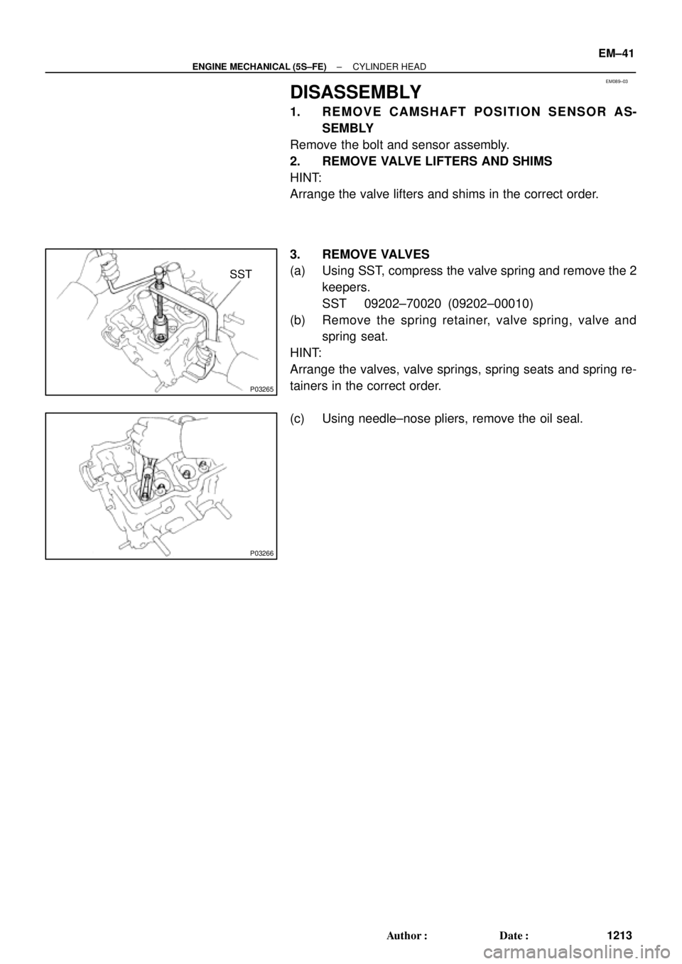
DISASSEMBLY
1. REMOVE CAMSHAFT POSITION SENSOR AS-
SEMBLY
Remove the bolt and sensor assembly.
2. REMOVE VALVE LIFTERS AND SHIMS
HINT:
Arrange the valve lifters and shims in the correct order.
3. REMOVE VALVES
(a) Using SST, compress the valve spring and remove the 2
keepers.
SST 09202±70020 (09202±00010)
(b) Remove the spring retainer, valve spring, valve and
spring seat.
HINT:
Arrange the valves, valve springs, spring seats and spring re-
tainers in the correct order.
(c) Using needle±nose pliers, remove the oil seal.
Page 3439 of 4770
CYLINDER HEAD
EM±47
1219 Author�: Date�:
(c) Using a spring tester, measure the tension of the valve
spring at the specif")
EM0281
EM1628
EM2011
EM2538
EM3322
Free Distance
± ENGINE MECHANICAL (5S±FE)CYLINDER HEAD
EM±47
1219 Author�: Date�:
(c) Using a spring tester, measure the tension of the valve
spring at the specified installed length.
Installed tension:
164 ± 189 N (16.7 ± 19.3 kgf, 36.8 ± 42.5 lbf)
at 34.7 mm (1.366 in.)
If the installed tension is not as specified, replace the valve
spring.
10. INSPECT CAMSHAFTS
(a) Inspect the circle runout.
(1) Place the camshaft on V±blocks.
(2) Using a dial indicator, measure the circle runout at
the center journal.
Maximum circle runout: 0.04 mm (0.0016 in.)
If the circle runout is greater than maximum, replace the cam-
shaft.
(b) Using a micrometer, measure the cam lobe height.
Standard cam lobe height:
Intake42.01 ± 42.11 mm (1.6539 ± 1.6579 in.)
Exhaust40.06 ± 40.16 mm (1.5772 ± 1.5811 in.)
Minimum cam lobe height:
Intake41.90 mm (1.6496 in.)
Exhaust39.95 mm (1.5728 in.)
If the cam lobe height is less than minimum, replace the cam-
shaft.
(c) Using a micrometer, measure the journal diameter.
Journal diameter:
26.959 ± 26.975 mm (1.0614 ± 1.0620 in.)
If the journal diameter is not as specified, check the oil clear-
ance.
(d) Using vernier calipers, measure the free distance be-
tween the gear spring ends.
Free distance: 22.5 ± 22.9 mm (0.886 ± 0.902 in.)
If the free distance is not as specified, replace the gear spring.
Page 3440 of 4770
CYLINDER HEAD
1220 Author�: Date�:
(e) Inspect the journal oil clearance.
(1) Clean the bearing caps and camshaft journals.
(")
EM3371
Plastigage
P00259
EM3310
P00263
EM±48
± ENGINE MECHANICAL (5S±FE)CYLINDER HEAD
1220 Author�: Date�:
(e) Inspect the journal oil clearance.
(1) Clean the bearing caps and camshaft journals.
(2) Check that bearings for flaking and scoring.
If the bearings are damaged, replace the bearing caps and cyl-
inder head as a set.
(3) Place the camshafts on the cylinder head.
(4) Lay a strip of Plastigage across each of the cam-
shaft journals.
(5) Install the bearing caps. (See page EM±53)
NOTICE:
Do not turn the camshaft.
(6) Remove the bearing caps.
(7) Measure the Plastigage at its widest point.
Standard oil clearance:
0.025 ± 0.062 mm (0.0010 ± 0.0024 in.)
Maximum oil clearance: 0.10 mm (0.0039 in.)
If the oil clearance is greater than maximum, replace the cam-
shaft. If necessary, replace the bearing caps and cylinder head
as a set.
(8) Completely remove the Plastigage.
(f) Inspect the camshaft thrust clearance.
(1) Install the camshaft. (See page EM±53)
(2) Using a dial indicator, measure the thrust clearance
while moving the camshaft back and forth.
Standard thrust clearance:
Intake0.045 ± 0.100 mm (0.0018 ± 0.0039 in.)
Exhaust0.030 ± 0.085 mm (0.0012 ± 0.0033 in.)
Maximum thrust clearance:
Intake0.12 mm (0.0047 in.)
Exhaust0.10 mm (0.0039 in.)
If the thrust clearance is greater than maximum, replace the
camshaft. If necessary, replace the bearing caps and cylinder
head as a set.
Page 3441 of 4770
CYLINDER HEAD
EM±49
1221 Author�: Date�:
(g) Inspect the camshaft gear backlash.
(1) Install the camshafts without installing the exhau")
EM3308
P03368
EM2196
S06013
S05606
± ENGINE MECHANICAL (5S±FE)CYLINDER HEAD
EM±49
1221 Author�: Date�:
(g) Inspect the camshaft gear backlash.
(1) Install the camshafts without installing the exhaust
cam sub±gear. (See page EM±53)
(2) Using a dial indicator, measure the backlash.
Standard backlash:
0.020 ± 0.200 mm (0.0008 ± 0.0079 in.)
Maximum backlash: 0.30 mm (0.0188 in.)
If the backlash is greater then maximum, replace the cam-
shafts.
11. INSPECT VALVE LIFTERS AND LIFTER BORES
(a) Using a caliper gauge, measure the lifter bore diameter
of the cylinder head.
Lifter bore diameter:
31.000 ± 31.018 mm (1.2205 ± 1.2212 in.)
(b) Using a micrometer, measure the lifter diameter.
Lifter diameter:
30.966 ± 30.976 mm (1.2191 ± 1.2195 in.)
(c) Subtract the lifter diameter measurement from the lifter
bore diameter measurement.
Standard oil clearance:
0.024 ± 0.052 mm (0.0009 ± 0.0020 in.)
Maximum oil clearance: 0.07 mm (0.0028 in.)
If the oil clearance is greater than maximum, replace the lifter.
If necessary, replace the cylinder head.
12. INSPECT INTAKE MANIFOLD
Using a precision straight edge and feeler gauge, measure the
surface contacting the cylinder head for warpage.
Maximum warpage: 0.30 mm (0.0118 in.)
If warpage is greater than maximum, replace the manifold.
13. INSPECT EXHAUST MANIFOLD
Using a precision straight edge and feeler gauge, measure the
surface contacting the cylinder head for warpage.
Maximum warpage: 0.30 mm (0.0118 in.)
If warpage is greater than maximum, replace the manifold.