Page 120 of 4770
B. Install exhaust camshaft
(a) Set the knock pin of the intake camshaft at 10±455
BTDC of camshaft angle.
HINT: The above angle allows the No.2 and No.4
cylinder cam lobes of the exhaust camshaft to push
their valve lifters evenly.(e) Apply a light coat of engine oil on the threads and
under the heads of the bearing cap bolts.
(f) Install and uniformly tighten the 10 bearing cap bolts
in several passes, in the sequence shown.
Torque: 19 N±m (190 kgf±cm, 14 ft±lbf)
(h) Using SST, tap in the oil seal.
SST 09223±4601 1 (d) Install the bearing caps in their proper locations.
(g) Apply MP grease to a new oil seal lip.
± 5S±FE ENGINEENGINE MECHANICALEG1±70
Page 121 of 4770

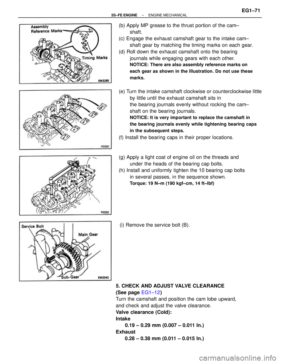
(b) Apply MP grease to the thrust portion of the cam±
shaft.
(c) Engage the exhaust camshaft gear to the intake cam±
shaft gear by matching the timing marks on each gear.
(d) Roll down the exhaust camshaft onto the bearing
journals while engaging gears with each other.
NOTICE: There are also assembly reference marks on
each gear as shown in the Illustration. Do not use these
marks.
5. CHECK AND ADJUST VALVE CLEARANCE
(See page EG1±12)
Turn the camshaft and position the cam lobe upward,
and check and adjust the valve clearance.
Valve clearance (Cold):
Intake
0.19 ± 0.29 mm (0.007 ± 0.011 In.)
Exhaust
0.28 ± 0.38 mm (0.011 ± 0.015 In.)(e) Turn the intake camshaft clockwise or counterclockwise little
by little until the exhaust camshaft sits in
the bearing journals evenly without rocking the cam±
shaft on the bearing journals.
NOTICE: It is very important to replace the camshaft in
the bearing journals evenly while tightening bearing caps
in the subsequent steps.
(f) Install the bearing caps in their proper locations.
(g) Apply a light coat of engine oil on the threads and
under the heads of the bearing cap bolts.
(h) Install and uniformly tighten the 10 bearing cap bolts
in several passes, in the sequence shown.
Torque: 19 N±m (190 kgf±cm, 14 ft±lbf)
(i) Remove the service bolt (B).
± 5S±FE ENGINEENGINE MECHANICALEG1±71
Page 124 of 4770
13. TEMPORARILY INSTALL NO.1 IDLER PULLEY AND
TENSION SPRING
(a) Install the pulley with the bolt. Do not tighten the bolt
yet.
HINT: Use bolt 42 mm (1.65 in.) in length.
(b) Install the tension spring.
(c) Pry the pulley toward the left as far as it will go and
tighten the bolt.
(d) Check that the idler pulley moves smoothly.
14. INSTALL CAMSHAFT TIMING PULLEY AND
TIMING BELT
(See page EG1±33)
15. INSTALL INJECTORS AND DELIVERY PIPE
(a) California:
Install new insulator and grommet to each injector.
(b) Except California:
Install a new grommet to each injector.
(c) California:
Apply a light coat of gasoline to 2 new 0±rings, and
install them to each injector.
(d) Except California:
Apply a light coat of gasoline to a new 0±ring, and
install it to each injector.
(e) While turning the injector left and right, install it to the
delivery pipes. Install the 4 injectors.
± 5S±FE ENGINEENGINE MECHANICALEG1±74
Page 191 of 4770
Cylinder head surface warpage
Cylinder bore diameterJournal diameter
Circle runout
Cam lobe height
Camshaft gear spring end free distance
Piston ring groove clearanceCamshaft gear backlash
Piston and
piston ring
Piston ring end gapJournal oil clearance
Piston oil clearanceThrust clearance
Piston diameter Cylinder blockCamshaft
± 5S±FE ENGINEENGINE MECHANICALEG1±141
Page 193 of 4770
Backlash
Crankshaft x No. 1 balance shaft
Off±vehicle
On±vehicle
No. 1 balance shaft x No.2 balance shaft
at D mark
at E mark
at F mark
Spacer thickness
Engine moving control rod x No. 2 engine mounting bracketCamshaft timing pulley x Camshaft (For use with SST)
TORQUE SPECIFICATIONS
No. 2 engine mounting bracket x Cylinder blockBalance shaft housing bolt outer diameter
Engine moving control rod X Fender apronOil pump pulley x Oil pump drive 'shaft Cylinder head cover x Cylinder head
Cylinder head x Cylinder block (1 styCamshaft timing pulley x Camshaft No. 2 idler pulley x Cylinder block
No. 1 idler pulley x Cylinder heedCrankshaft pulley x Crankshaft Spark plug x Cylinder headEngine
balancerThrust clearance
Part tightened
± 5S±FE ENGINEENGINE MECHANICALEG1±143
Page 194 of 4770

No. 1 balance shaft housing x No. 2 balance shaft housing (1st)
No. 1 balance shaft housing x No. 2 balance shaft housing (2nd)
FR engine mounting insulator x Front suspension member
RR engine mounting insulator x Front suspension member Exhaust manifold stay x FR engine mounting insulator No. 1 air intake chamber stay x Intake manifold
RR engine mounting insulator x Cylinder block
FR engine mounting insulator x Cylinder block No. 1 air intake chamber stay x Cylinder head
No. 1 exhaust manifold stay x Cylinder block
Connecting rod cap x Connecting rod (2nd) Connecting rod cap x Connecting rod (1 st)
LH engine mounting insulator x Transaxle No. 1 exhaust manifold stay x WU ±TWC Water bypass pipe x Water pump cover
Fuel inlet hose x Fuel filter (Union bolt) No. 3 timing belt cover x Cylinder head
Intake manifold stay x Intake manifoldCamshaft bearing cap x Cylinder head
Intake manifold stay x Cylinder blockCylinder head x Cylinder block (2nd)
Rear oil seal retainer x Cylinder block Exhaust manifold stay x WU ±TWC
PS pump bracket x Cylinder block Main bearing cap x Cylinder block Generator bracket x Cylinder head
A/C compressor x Cylinder block Pulsation damper x Delivery pipe
Exhaust manifold x Cylinder head
Engine balancer x Cylinder block
Front exhaust pipe x WU ±TWC Spark plug tube x Cylinder head
Rear end plate x Cylinder block Throttle body x Intake manifold Intake manifold x Cylinder heedEngine hanger x Cylinder head
Drive plate x Crankshaft (A/T)Knock sensor x Cylinder block Delivery pipe x Cylinder head
PS pump x PS pump bracketWU±TWC x Exhaust manifold
Flywheel x Crankshaft (M/T) Water outlet x Cylinder headEGR valve x intake manifold
EGR pipe x Cylinder head
± 5S±FE ENGINEENGINE MECHANICALEG1±144
Page 521 of 4770

42ENGINEÐ5S±FE ENGINE
5. Main Components of Engine Control System
The following table compares the main components of the new 5S±FE engine, and previous 5S±FE engine.
Model
NewPreviousComponentNewPrevious
Manifold Absolute Pressure SensorSemiconductoru
Throttle Position SensorLinear Typeu
Crankshaft Position SensorPick±Up Coil Type, 1u
Camshaft Position SensorPick±Up Coil Type, 1Ð
DistributorCamshaft PositionPick Up Coil Type 1DistributorSensorÐPick±Up Coil Type, 1
Knock SensorBuilt±In Piezoelectric
Element Type 1u
Oxygen Sensor
Heated Oxygen Sensor
(Bank 1, Sensor 1)*
1
(Bank 1, Sensor 2)
Air Fuel Ratio Sensor*
2
Oxygen Sensor
(Bank 1, Sensor 1)
(Bank 1, Sensor 2)
Injector2±Hole Typeu
IAC ValveRotary Solenoid Typeu
*1: Except for California Specification Models.
*
2: Only for California Specification Models.
Camshaft Position Sensor
The camshaft position sensor is mounted onto the
cylinder head. Using the protusion that is provided
on the timing pulley, the sensor generates 1 signal
for every revolution. This signal is then sent to the
ECM as a cranskshaft angle system.
Page 720 of 4770

CAMRY ± NEW FEATURES
No.2 INJECTOR
SENSORS ACTUATORS
VG
RSO IGF NE
ECM
IGTI�
IGT3
#10
G22
THW
THA
VTA1
STA
SPD
AFR
AFL
OXS
EGLS
THG
KNKR
CF
NSW
A/C
ACIS
FC
ACT
MAFR
HAFL
HREL
#20
#30
#40
#50
#60
MASS AIR FLOW METER
R, 2, L KNKLIGSW
RSC
CRANKSHAFT POSITION SENSOR
�Engine Speed Signal
�Crankshaft Angle Signal
CAMSHAFT POSITION SENSOR
�Crankshaft Angle Signal
ENGINE COOLANT TEMP.
SENSOR
INTAKE AIR TEMP. SENSOR
THROTTLE POSITION SENSOR
�Throttle Position Signal
IGNITION SWITCH
�Starting Signal
�Ignition Signal
VEHICLE SPEED SENSOR
COMBINATION METER
AIR-FUEL RATIO SENSOR
(Bank 1, Sensor 1)
AIR-FUEL RATIO SENSOR
(Bank 2, Sensor 1)
HEATED OXYGEN SENSOR
(Bank 1, Sensor 2)
EGR VALVE POSITION SENSOR
EGR GAS TEMP. SENSOR
KNOCK SENSORS
PARK / NEUTRAL POSITION
SWITCH
�Neutral Start Signal
AIR CONDITIONING AMPLIFIER
�A / C Switch Signal
COOLING FAN RELAYNo.1 INJECTOR
No.3 INJECTOR
No.4 INJECTOR
No.5 INJECTOR
No.6 INJECTOR
ESA
IGNITER
IGNITION COILS
SPARK PLUGS
IAC
CONTROL VALVE
ACIS
VSV
FUEL PUMP CONTROL
CIRCUIT OPENING RELAY
AIR CONDITIONING CONTROL
AIR CONDITIONING
AMPLIFIER
AIR FUEL RATIO SENSOR
HEATER CONTROL
AIR FUEL RATIO SENSOR
HEATER RELAY
AIR FUEL RATIO SENSOR
HEATER (Bank 1, Sensor 1)
AIR FUEL RATIO SENSOR
HEATER (Bank 1, Sensor 2)SFI
(Continued)
KNOCK SENSORS
11
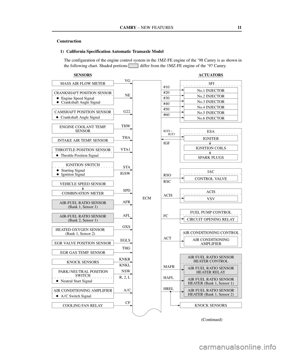
Construction
1) California Specification Automatic Transaxle Model
The configuration of the engine control system in the 1MZ-FE engine of the '98 Camry is as shown in
the following chart. Shaded portions
differ from the 1MZ-FE engine of the '97 Camry.