Page 101 of 4770

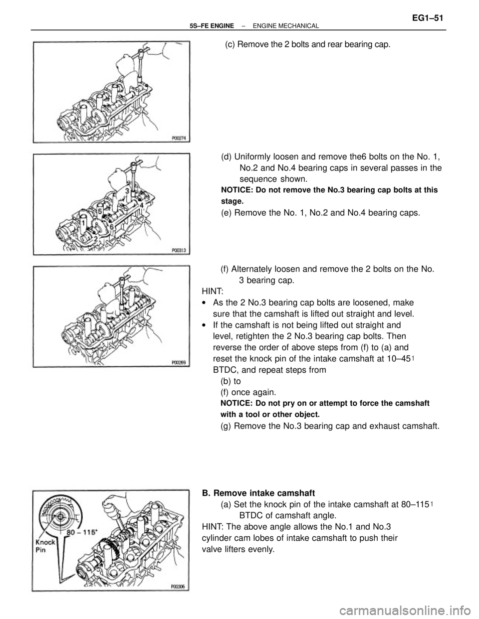
(f) Alternately loosen and remove the 2 bolts on the No.
3 bearing cap.
HINT:
wAs the 2 No.3 bearing cap bolts are loosened, make
sure that the camshaft is lifted out straight and level.
wIf the camshaft is not being lifted out straight and
level, retighten the 2 No.3 bearing cap bolts. Then
reverse the order of above steps from (f) to (a) and
reset the knock pin of the intake camshaft at 10±45�
BTDC, and repeat steps from
(b) to
(f) once again.
NOTICE: Do not pry on or attempt to force the camshaft
with a tool or other object.
(g) Remove the No.3 bearing cap and exhaust camshaft.(d) Uniformly loosen and remove the6 bolts on the No. 1,
No.2 and No.4 bearing caps in several passes in the
sequence shown.
NOTICE: Do not remove the No.3 bearing cap bolts at this
stage.
(e) Remove the No. 1, No.2 and No.4 bearing caps.
B. Remove intake camshaft
(a) Set the knock pin of the intake camshaft at 80±115�
BTDC of camshaft angle.
HINT: The above angle allows the No.1 and No.3
cylinder cam lobes of intake camshaft to push their
valve lifters evenly.(c) Remove the 2 bolts and rear bearing cap.
± 5S±FE ENGINEENGINE MECHANICALEG1±51
Page 102 of 4770

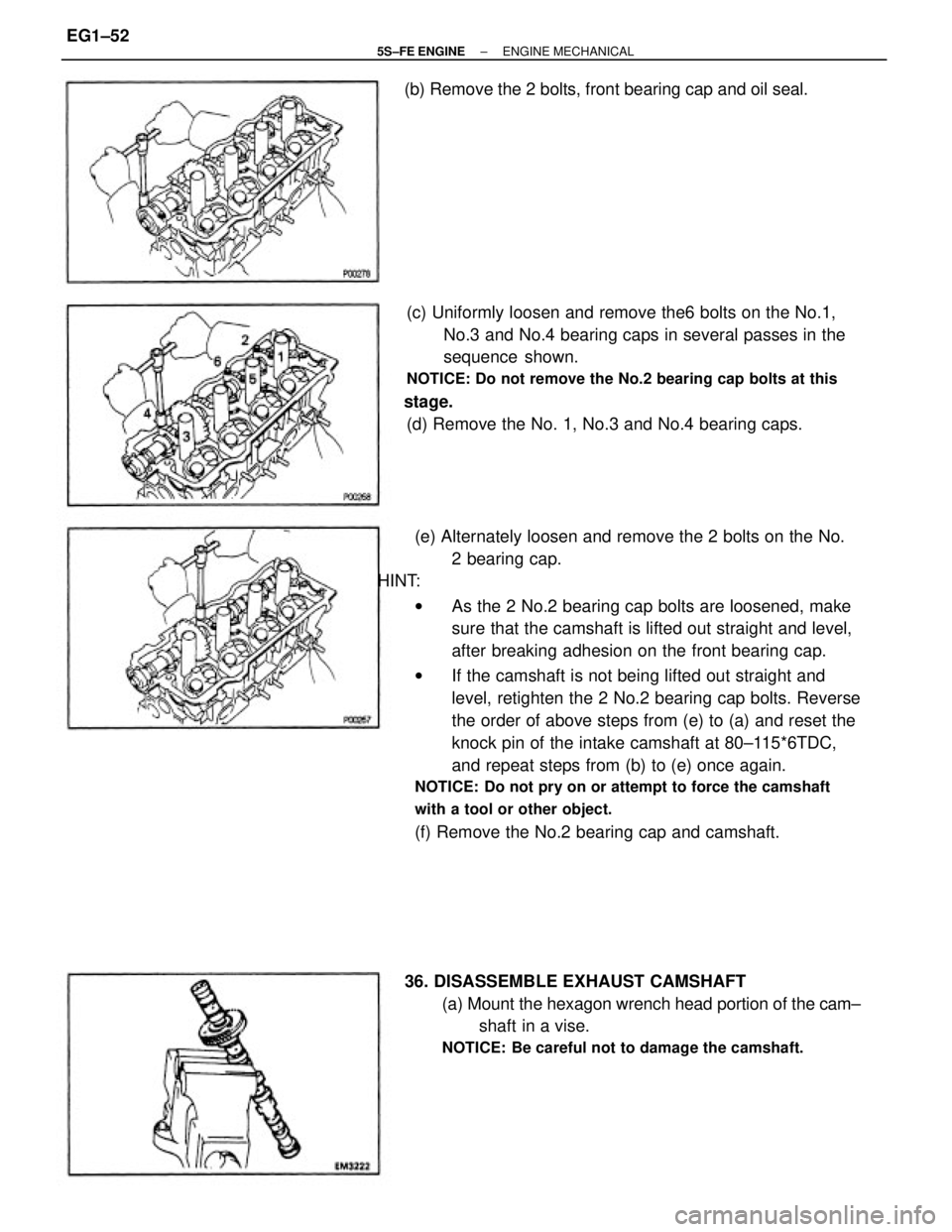
(e) Alternately loosen and remove the 2 bolts on the No.
2 bearing cap.
HINT:
wAs the 2 No.2 bearing cap bolts are loosened, make
sure that the camshaft is lifted out straight and level,
after breaking adhesion on the front bearing cap.
wIf the camshaft is not being lifted out straight and
level, retighten the 2 No.2 bearing cap bolts. Reverse
the order of above steps from (e) to (a) and reset the
knock pin of the intake camshaft at 80±115*6TDC,
and repeat steps from (b) to (e) once again.
NOTICE: Do not pry on or attempt to force the camshaft
with a tool or other object.
(f) Remove the No.2 bearing cap and camshaft. (c) Uniformly loosen and remove the6 bolts on the No.1,
No.3 and No.4 bearing caps in several passes in the
sequence shown.
NOTICE: Do not remove the No.2 bearing cap bolts at this
stage.
(d) Remove the No. 1, No.3 and No.4 bearing caps.
36. DISASSEMBLE EXHAUST CAMSHAFT
(a) Mount the hexagon wrench head portion of the cam±
shaft in a vise.
NOTICE: Be careful not to damage the camshaft.
(b) Remove the 2 bolts, front bearing cap and oil seal.
± 5S±FE ENGINEENGINE MECHANICALEG1±52
Page 103 of 4770
37. REMOVE CYLINDER HEAD
(a) Using SST, uniformly loosen and remove the 10 cylin±
der head bolts in several passes, in the sequence
shown.
SST 09011± 38121
NOTICE: Cylinder head warpage or cracking could result
from removing bolts in incorrect order.
(b) Insert a service bolt (A) into the service hole of the
camshaft sub gear.
(c) Using a screwdriver, turn the sub gear clockwise, and
remove the service bolt (B).
NOTICE: Be careful not to damage the camshaft.
(e) Remove the following parts:
(1) Wave washer
(2) Camshaft sub gear
(3) Camshaft gear spring (d) Using snap ring pliers, remove the snap ring.
± 5S±FE ENGINEENGINE MECHANICALEG1±53
Page 112 of 4770

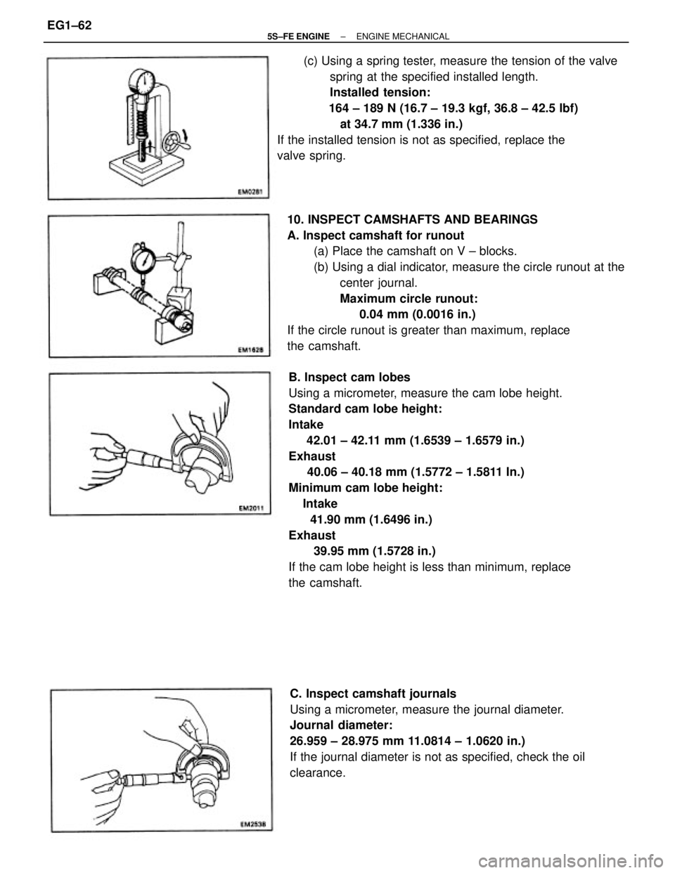
B. Inspect cam lobes
Using a micrometer, measure the cam lobe height.
Standard cam lobe height:
Intake
42.01 ± 42.11 mm (1.6539 ± 1.6579 in.)
Exhaust
40.06 ± 40.18 mm (1.5772 ± 1.5811 In.)
Minimum cam lobe height:
Intake
41.90 mm (1.6496 in.)
Exhaust
39.95 mm (1.5728 in.)
If the cam lobe height is less than minimum, replace
the camshaft. 10. INSPECT CAMSHAFTS AND BEARINGS
A. Inspect camshaft for runout
(a) Place the camshaft on V ± blocks.
(b) Using a dial indicator, measure the circle runout at the
center journal.
Maximum circle runout:
0.04 mm (0.0016 in.)
If the circle runout is greater than maximum, replace
the camshaft.(c) Using a spring tester, measure the tension of the valve
spring at the specified installed length.
Installed tension:
164 ± 189 N (16.7 ± 19.3 kgf, 36.8 ± 42.5 lbf)
at 34.7 mm (1.336 in.)
If the installed tension is not as specified, replace the
valve spring.
C. Inspect camshaft journals
Using a micrometer, measure the journal diameter.
Journal diameter:
26.959 ± 28.975 mm 11.0814 ± 1.0620 in.)
If the journal diameter is not as specified, check the oil
clearance.
± 5S±FE ENGINEENGINE MECHANICALEG1±62
Page 113 of 4770
E. Inspect camshaft gear spring
Using a vernier caliper, measure the free distance
between the spring ends.
Free distance:
22.5 ± 22.9 mm (0.886 ± 0.902 in.)
If the free distance is not as specified, replace the gear
spring.
F. Inspect camshaft journal oil clearance
(a) Clean the bearing caps and camshaft journals.
(b) Place the camshafts on the cylinder head.
(c) Lay a strip of Plastigage across each of the camshaft
journals. D. Inspect camshaft bearings
Check that bearings for flaking and scoring.
If the bearings are damaged, replace the bearing caps
and cylinder head as a set.
(d) Install the bearing caps.
(See step 4 on pages EG1±69 to 71)
Torque: 19 N±m (190 kgf±cm, 14 ft±lbf)
NOTICE: Do not turn the camshaft.
(e) Remove the bearing caps.
± 5S±FE ENGINEENGINE MECHANICALEG1±63
Page 114 of 4770

G. Inspect camshaft thrust clearance
(a) Install the camshaft.
(See step 4 on pages EG1±69 to 71)
(b) Using a dial indicator, measure the thrust clearance
while moving the camshaft back and forth.
Standard thrust clearance:
Intake
0.045 ± 0.100 mm (0.0018 ± 0.0039 in.)
Exhaust
0.030 ± 0.085 mm (0.0012 ± 0.0033 in.)
Maximum thrust clearance:
Intake
0.12 mm (0.0047 in.)
Exhaust
0.10 mm (0.0039 in.)
If the thrust clearance is greater than maximum, re±
place the camshaft. If necessary, replace the bearing
caps and cylinder head as a set.
H. Inspect camshaft gear backlash
(a) Install the camshafts without installing the exhaust
cam sub gear.
(See step 4 on pages EG1±69 to 71)
(b) Using a dial indicator, measure the backlash.
Standard backlash:
0.020 ± 0.200 mm (0.0008 ± 0.0079 in.)
Maximum backlash:
6.30 mm (0.0188 in.)
If the backlash is greater then maximum, replace the
camshafts. (f) Measure the Plastigage at its widest point.
Standard oil clearance:
0.025 ± 0.062 mm (0.0010 ± 0.0024 In.)
Maximum oil clearance:
0.10 mm (0.0039 in.)
If the oil clearance is greater than maximum, replace
the camshaft. If necessary, replace the bearing caps
and cylinder head as a set.
(g) Completely remove the Plastigage.
± 5S±FE ENGINEENGINE MECHANICALEG1±64
Page 118 of 4770
2. INSTALL SPARK PLUG TUBES
(a) Clean the cylinder head tube holes of any residua!
adhesive, oil or foreign particles. Remove any oil with
kerosene or gasoline.
(b) Screw the threads of the spark plug tube coated with
adhesive into the cylinder head.
(c) Using the spark plug tube nut and a 30 mm socket
wrench, tighten the spark plug tubes.
Torque: 39 N±m (400 kgf±cm, 29 ft±lbf)
(b) Install the following parts:
(1) Camshaft gear spring
(2) Camshaft sub gear
(3) Wave washer
HINT: Align the pins on the gears with the spring ends.(d) Retighten the cylinder head bolts 90� in the sequence
shown on the previous page.
(e) Check that the painted mark is now at a 90� angle to
front.
3. ASSEMBLY EXHAUST CAMSHAFT
(a) Mount the hexagon wrench head portion of the cam±
shaft in a vise.
NOTICE: Be careful not to damage the camshaft.
(c) Mark the front of the cylinder head bolt head with
paint.
± 5S±FE ENGINEENGINE MECHANICALEG1±68
Page 119 of 4770

A. Install intake camshaft
(a) Apply MP grease to the thrust portion of the cam±
shaft.
(b) Place the intake camshaft at 80±1155 BTDC of cam±
shaft angle, on the cylinder head.
HINT: The above angle arrows the No.1 and No.3
cylinder cam lobes of the intake camshaft to push
their valve lifters evenly. 4. INSTALL CAMSHAFTS
NOTICE: Since the thrust clearance of the camshaft is
small, the camshaft must be kept level while it is being
installed. If the camshaft is not kept level, the portion of
the cylinder head receiving the shaft thrust may crack or
be damaged, causing the camshaft to seize or break. To
avoid this, the following steps should be carried out.
(d) Insert a service bolt (A) into the service hole of the
camshaft sub gear.
(e) Using a screwdriver, align the holes of the camshaft
main gear and sub gear by turning camshaft sub gear
clockwise, and install a service bolt (13).
NOTICE: Be careful not to damage the camshaft.
(c) Apply seal packing to the No. 1 bearing cap as shown.
Seal packing:
Part No.08826 ±00080 or equivalent (c) Using snap ring pliers, install the snap ring.
± 5S±FE ENGINEENGINE MECHANICALEG1±69