Page 63 of 4770

4. INSPECT VALVE CLEARANCE
(a) Check only the valves indicated.
Using a thickness gauge, measure the clearance
between the valve lifter and camshaft.
Record the out± of ±specification valve clear±
ance measurements. They will be used later to
determine the required replacement adjusting
shim.
Valve clearance (Cold):
Intake
0.19 ± 0.29 mm (0.007 ± 0.011 in.)
Exhaust
0.28 ± 0.38 mm (0.011 ± 0.015 in.) 3. SET NO.1 CYLINDER TO TDC/COMPRESSION
(a) Turn the crankshaft pulley and align its groove with
timing mark ª0º of the No.1 timing belt cover.
(b) Check that the valve lifters on the No.1 cylinder are
loose and valve lifters on the No.4 are tight.
If not, turn the crankshaft one revolution (360*) and
align the mark as above.
(b) Turn the crankshaft one revolution (360�) and align
the mark as above. (See procedure in step 3)
(c) Check only the valves indicated as shown. Measure
the valve clearance. (See procedure in step (a)) HINT: Arrange the grommets in correct order, so that
they can be reinstalled into their original positions.
This minimizes any possibility of oil leakage due to
reuse of grommets.
± 5S±FE ENGINEENGINE MECHANICALEG1±13
Page 64 of 4770

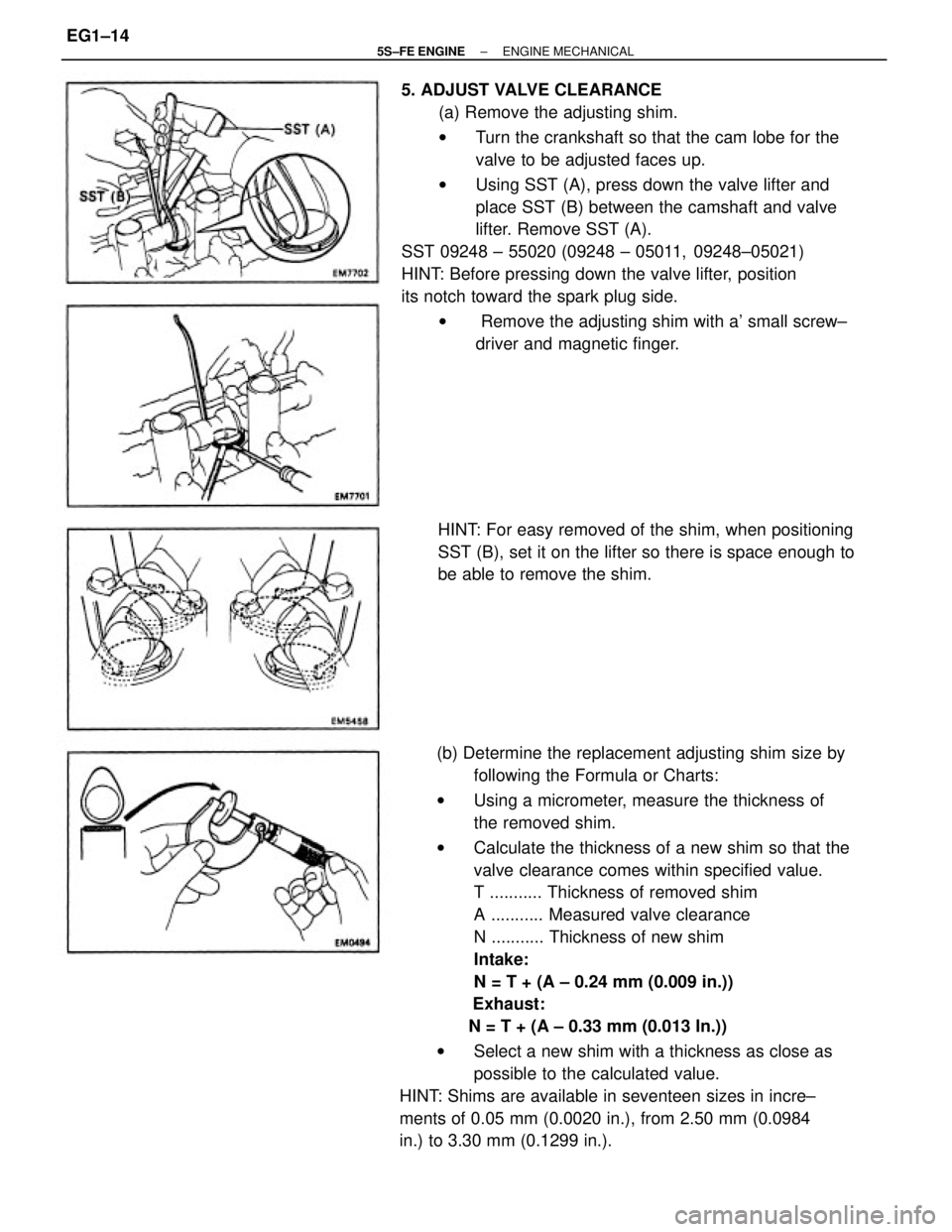
(b) Determine the replacement adjusting shim size by
following the Formula or Charts:
wUsing a micrometer, measure the thickness of
the removed shim.
wCalculate the thickness of a new shim so that the
valve clearance comes within specified value.
T ........... Thickness of removed shim
A ........... Measured valve clearance
N ........... Thickness of new shim
Intake:
N = T + (A ± 0.24 mm (0.009 in.))
Exhaust:
N = T + (A ± 0.33 mm (0.013 In.))
wSelect a new shim with a thickness as close as
possible to the calculated value.
HINT: Shims are available in seventeen sizes in incre±
ments of 0.05 mm (0.0020 in.), from 2.50 mm (0.0984
in.) to 3.30 mm (0.1299 in.).5. ADJUST VALVE CLEARANCE
(a) Remove the adjusting shim.
wTurn the crankshaft so that the cam lobe for the
valve to be adjusted faces up.
wUsing SST (A), press down the valve lifter and
place SST (B) between the camshaft and valve
lifter. Remove SST (A).
SST 09248 ± 55020 (09248 ± 05011, 09248±05021)
HINT: Before pressing down the valve lifter, position
its notch toward the spark plug side.
w Remove the adjusting shim with a' small screw±
driver and magnetic finger.
HINT: For easy removed of the shim, when positioning
SST (B), set it on the lifter so there is space enough to
be able to remove the shim.
± 5S±FE ENGINEENGINE MECHANICALEG1±14
Page 78 of 4770
14. REMOVE TIMING BELT FROM CAMSHAFT TIMING
PULLEY
HINT (When re±using timing belt): Place the match±
marks on the timing belt and camshaft timing pulley,
and place matchmark on timing belt to match the end
of the No.1 timing belt cover.
15. REMOVE CAMSHAFT TIMING PULLEY
Using SST, remove the bolt, plate washer and timing
pulley.
SST 09249±63010 and 09278±54012(b) Check that the hole of the camshaft timing pulley is
aligned with the timing mark of the bearing cap.
If not, turn the crankshaft one revolution (360'*).
(a) Loosen the mounting bolt of the No.1 idler pulley and
shift the pulley toward the left as far as it will go, and
temporarily tighten it.
(b) Remove the timing belt from the camshaft timing
pulley.
± 5S±FE ENGINEENGINE MECHANICALEG1±28
Page 82 of 4770
wDo not utilize timing belt tension when installing or
removing the mounting bolt of the camshaft timing
pulley.
If there are any defects as shown in the illustration,
check the following points:
(a) Premature parting
wCheck for proper installation.
wCheck the timing cover gasket for damage and
proper installation.
(b) If the belt teeth are cracked or damaged, check to see
if either camshaft or water pump is locked.
(e) If there is noticeable wear on the belt teeth, check the
timing cover for damage, correct gasket installation,
and for foreign material on the pulley teeth.
If necessary, replace the timing belt. (c) If there is noticeable wear or cracks on the belt face,
check to see if there are nicks on the side of the idler
pulley lock.
(d) If there is wear or damage on only one side of the belt,
check the belt guide and the alignment of each pulley.
± 5S±FE ENGINEENGINE MECHANICALEG1±32
Page 85 of 4770
9. INSTALL CAMSHAFT TIMING PULLEY
(a) Align the camshaft knock pin with the knock pin
groove of the pulley, and slide on the timing pulley.
(b) Using SST, install the plate washer and bolt.
SST 09249 ± 63010 and 09278 ± 54012
Torque: 37 N±m (380 kgf±cm, 27 ft±lbf)
HINT: Use a torque wrench with a fulcrum length of
340 cm (13.39 in.)8. INSTALL CRANKSHAFT PULLEY
(a) Align the pulley set key with the key groove of the
pulley, and slide on the pulley.
(b) Using SST, install the pulley bolt.
SST 09213±54015 (91651 ±60855)
09330±00021
Torque: 108 N±m (1,100 kgf±cm, 80 ft±lbf)
10. SET No.1 CYLINDER TO TDC/COMPRESSION
(a) Turn the crankshaft pulley, and align its groove with
timing mark ª0º of the No.1 timing belt cover. 7. INSTALL NO.1 TIMING BELT COVER
(a) Install the gasket to the timing belt cover.
(b) Install the timing belt cover with the 4 bolts. 6. INSTALL TIMING BELT GUIDE
Install the guide, facing the cup side outward.
± 5S±FE ENGINEENGINE MECHANICALEG1±35
Page 86 of 4770
11. INSTALL TIMING BELT
HINT. (When re±using timing belt):
wCheck that the matchmark on the timing belt
matches the end of the No.1 timing belt cover.
If the matchmark does not align, shift the meshing of
the timing belt and crankshaft timing pulley until they
align. (See page EG1±29)
(a) Remove any oil or water on the camshaft timing
pulley, and keep it clean.
(b) Install the timing belt, and check the tension between
the crankshaft timing pulley and camshaft timing
pulley. (b) Using SST, turn the camshaft, and align the hole of
the camshaft timing pulley with the timing mark of the
bearing cap.
SST 09278±54012
wAlign the matchmarks of the timing belt and
camshaft timing pulley.
12. CHECK VALVE TIMING
(a) Loosen the No.1 idler pulley bolt 1/2 turn.
± 5S±FE ENGINEENGINE MECHANICALEG1±36
Page 99 of 4770
NOTICE:
wSupport the timing belt, :o the meshing of crank±
shaft timing pulley and timing belt does not shift.
wBe careful not to drop anything inside the timing
belt cover.
wDo not allow the belt to come into correct with oil,
water or dust.
30. REMOVE ENGINE HANGERS
Remove the bolt and engine hanger. Remove the 2
engine hangers. Remove the ground strap.
31. REMOVE GENERATOR BRACKET
Remove the 3 bolts and generator bracket.
32. REMOVE OIL PRESSURE SWITCH 27. REMOVE CAMSHAFT TIMING PULLEY
(See steps 2 to 15 on pages EG1±26 to 28)
28. REMOVE NO. 1 IDLER PULLEY AND TENSION
SPRING
Remove the bolt, pulley and tension spring.
33. REMOVE CYLINDER HEAD COVER
Remove the 4 nuts, grommets, head cover and gasket.29. REMOVE NO.3 TIMING BELT COVER
Remove the 4 bolts and timing and cover.
± 5S±FE ENGINEENGINE MECHANICALEG1±49
Page 100 of 4770

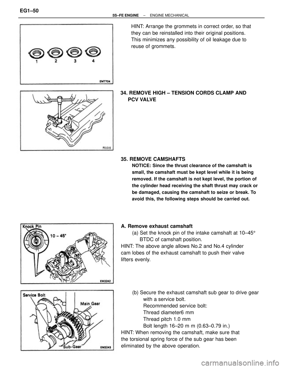
(b) Secure the exhaust camshaft sub gear to drive gear
with a service bolt.
Recommended service bolt:
Thread diameter6 mm
Thread pitch 1.0 mm
Bolt length 16±20 m m (0.63±0.79 in.)
HINT: When removing the camshaft, make sure that
the torsional spring force of the sub gear has been
eliminated by the above operation. 35. REMOVE CAMSHAFTS
NOTICE: Since the thrust clearance of the camshaft is
small, the camshaft must be kept level while it is being
removed. If the camshaft is not kept level, the portion of
the cylinder head receiving the shaft thrust may crack or
be damaged, causing the camshaft to seize or break. To
avoid this, the following steps should be carried out.
A. Remove exhaust camshaft
(a) Set the knock pin of the intake camshaft at 10±455
BTDC of camshaft position.
HINT: The above angle allows No.2 and No.4 cylinder
cam lobes of the exhaust camshaft to push their valve
lifters evenly.HINT: Arrange the grommets in correct order, so that
they can be reinstalled into their original positions.
This minimizes any possibility of oil leakage due to
reuse of grommets.
34. REMOVE HIGH ± TENSION CORDS CLAMP AND
PCV VALVE
± 5S±FE ENGINEENGINE MECHANICALEG1±50