Page 3556 of 4770
CYLINDER HEAD
1336 Author�: Date�:
(c) Remove the camshafts.
19. INSPECT CAMSHAFT GEAR BACKLASH
(a) Install the camshafts")
P12960
EM3322
Free Distance
P12685
EM6368
EM±50
± ENGINE MECHANICAL (1MZ±FE)CYLINDER HEAD
1336 Author�: Date�:
(c) Remove the camshafts.
19. INSPECT CAMSHAFT GEAR BACKLASH
(a) Install the camshafts without installing the exhaust cam
sub±gear. (See page EM±57)
(b) Using a dial indicator, measure the backlash.
Standard backlash:
0.020 ± 0.200 mm (0.0008 ± 0.0079 in.)
Maximum backlash: 0.30 mm (0.0188 in.)
If the backlash is greater then maximum, replace the cam-
shafts.
(c) Remove the camshafts.
20. INSPECT CAMSHAFT GEAR SPRING
Using vernier calipers, measure the free distance between the
spring ends.
Free distance: 18.2 ± 18.8 mm (0.712 ± 0.740 in.)
If the free distance is not as specified, replace the gear spring.
21. INSPECT VALVE LIFTERS AND LIFTER BORES
(a) Using a caliper gauge, measure the lifter bore diameter
of the cylinder head.
Lifter bore diameter:
31.000 ± 31.018 mm (1.2205 ± 1.2212 in.)
(b) Using a micrometer, measure the lifter diameter.
Lifter diameter:
30.966 ± 30.976 mm (1.2191 ± 1.2195 in.)
(c) Subtract the lifter diameter measurement from the lifter
bore diameter measurement.
Standard oil clearance:
0.024 ± 0.050 mm (0.0009 ± 0.0020 in.)
Maximum oil clearance: 0.07 mm (0.0028 in.)
If the oil clearance is greater than maximum, replace the lifter.
If necessary, replace the cylinder head.
Page 3561 of 4770
Adhesive
P12572
Protrusion
P12869
Flush
P12719
SST
± ENGINE MECHANICAL (1MZ±FE)CYLINDER HEAD
EM±55
1341 Author�: Date�:
REASSEMBLY
HINT:
�Thoroughly c")
EM04V±04
P1151110 ± 15 mm (0.39 ± 0.59 in.)Adhesive
P12572
Protrusion
P12869
Flush
P12719
SST
± ENGINE MECHANICAL (1MZ±FE)CYLINDER HEAD
EM±55
1341 Author�: Date�:
REASSEMBLY
HINT:
�Thoroughly clean all parts to be assembled.
�Before installing the parts, apply new engine oil to all slid-
ing and rotating surfaces.
�Replace all gaskets and oil seals with new ones.
1. INSTALL SPARK PLUG TUBES
HINT:
When using a new cylinder head, spark plug tubes must be
installed.
(a) Apply adhesive to the end of the spark plug tube.
Adhesive:
Part No. 08833±00070, THREE BOND 1324
or equivalent
(b) Using a press, press in a new spark plug tube until there
is 42.4 ± 43.4 mm (1.669 ± 1.709 in.) protruding from the
camshaft bearing cap installation surface of the cylinder
head.
NOTICE:
Avoid pressing a new spark plug tube in too far by measur-
ing the amount of the protrusion while pressing.
2. INSTALL PCV PIPES
HINT:
When using a new cylinder head, PCV pipe must be installed.
Using a wooden block and hammer, tap in a new PCV pipe until
its top side is flush with the cylinder head edge.
NOTICE:
Be careful not to damage the cylinder head edge.
3. INSTALL VALVES
(a) Using SST, push in a new oil seal.
SST 09201±41020
Page 3564 of 4770
P12814
Recessed Head Bolt
8 mm Hexagon Wrench
Front
P12595
Z09320
(3)
(2)
(1)
P12590
EM±58
± ENGINE MECHANICAL (1MZ±FE)CYLINDER HEAD
1344 Author�: Date�:
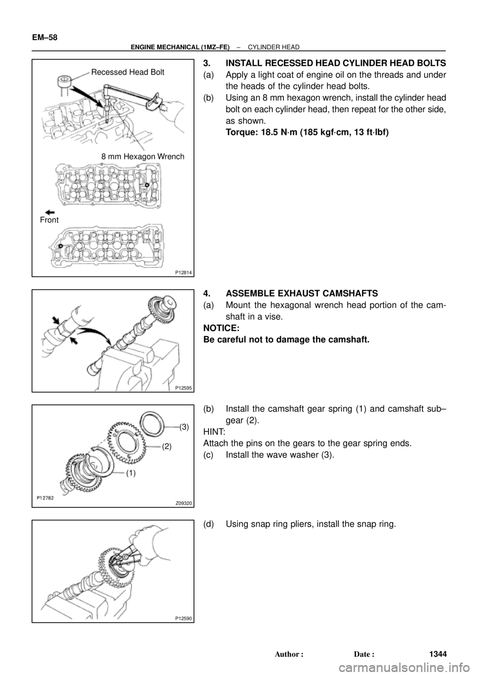
3. INSTALL RECESSED HEAD CYLINDER HEAD BOLTS
(a) Apply a light coat of engine oil on the threads and under
the heads of the cylinder head bolts.
(b) Using an 8 mm hexagon wrench, install the cylinder head
bolt on each cylinder head, then repeat for the other side,
as shown.
Torque: 18.5 N´m (185 kgf´cm, 13 ft´lbf)
4. ASSEMBLE EXHAUST CAMSHAFTS
(a) Mount the hexagonal wrench head portion of the cam-
shaft in a vise.
NOTICE:
Be careful not to damage the camshaft.
(b) Install the camshaft gear spring (1) and camshaft sub±
gear (2).
HINT:
Attach the pins on the gears to the gear spring ends.
(c) Install the wave washer (3).
(d) Using snap ring pliers, install the snap ring.
Page 3565 of 4770
CYLINDER HEAD
EM±59
1345 Author�: Date�:
(e) Using SST, align the hole")
P12974
SST
Main Gear
Sub±Gear
P12963
90°Exhaust
P12804
Exhaust
Front
A02008
Exhaust
Seal
Packing
± ENGINE MECHANICAL (1MZ±FE)CYLINDER HEAD
EM±59
1345 Author�: Date�:
(e) Using SST, align the holes of the camshaft main gear and
sub±gear by turning camshaft sub±gear counterclock-
wise, and temporarily install a service bolt.
SST 09960±10010 (09962±01000, 09963±00500)
(f) Align the gear teeth of the main gear and sub±gear, and
tighten the service bolt.
5. INSTALL CAMSHAFTS OF RH CYLINDER HEAD
NOTICE:
Since the thrust clearance of the camshaft is small, the
camshaft must be held level while it is being installed. If the
camshaft is not level, the portion of the cylinder head re-
ceiving the shaft thrust may crack or be damaged, causing
the camshaft to seize or break. To avoid this, the following
steps should be carried out.
(a) Install the exhaust camshaft.
(1) Apply new engine oil to the thrust portion and jour-
nal of the camshaft.
(2) Place the exhaust camshaft at 90° angle of timing
mark (2 dot marks) on the cylinder head.
(3) Apply MP grease to a new oil seal lip.
(4) Install the oil seal to the camshaft.
(5) Remove any old packing (FIPG) material.
(6) Apply seal packing to the No.1 bearing cap as
shown.
Seal packing: Part No. 08826±00080 or equivalent
Page 3566 of 4770
CYLINDER HEAD
1346 Author�: Date�:
(b) Install th")
P12890
Exhaust
P12887
Exhaust
8
76
5
4
32
19 10
P12875
Intake
Align
P12798
Intake
P25422
Intake
8 76 5
4 32 19
10
EM±60
± ENGINE MECHANICAL (1MZ±FE)CYLINDER HEAD
1346 Author�: Date�:
(b) Install the 5 bearing caps in their proper locations.
(c) Apply a light coat of engine oil on the threads and under
the heads of the bearing cap bolts.
(d) Install and uniformly tighten the 10 bearing cap bolts, in
several passes, in the sequence shown.
Torque: 16 N´m (160 kgf´cm, 12 ft´lbf)
(e) Install the Intake camshaft.
(1) Apply new engine oil to the thrust portion and jour-
nal of the camshaft.
(2) Align the timing marks (2 dot marks) of the camshaft
drive and driven gears.
(3) Place the intake camshaft on the cylinder head.
(4) Install the 5 bearing caps in their proper locations.
(5) Apply a light coat of engine oil on the threads and
under the heads of the bearing cap bolts.
(6) Install and uniformly tighten the 10 bearing cap
bolts, in several passes, in the sequence shown.
Torque: 16 N´m (160 kgf´cm, 12 ft´lbf)
Page 3567 of 4770
CYLINDER HEAD
EM±61
1347 Author�: Date�:
(7) Remove the service bolt.
6. I")
P12870Service Bolt
Intake
P12884
Exhaust
90°
P12805
Exhaust
Front
A02008
Exhaust
Seal
Packing
± ENGINE MECHANICAL (1MZ±FE)CYLINDER HEAD
EM±61
1347 Author�: Date�:
(7) Remove the service bolt.
6. INSTALL CAMSHAFTS OF LH CYLINDER HEAD
NOTICE:
Since the thrust clearance of the camshaft is small, the
camshaft must be held level while it is being installed. If the
camshaft is not level, the portion of the cylinder head re-
ceiving the shaft thrust may crack or be damaged, causing
the camshaft to seize or break. To avoid this, the following
steps should be carried out.
(a) Install the exhaust camshaft.
(1) Apply new engine oil to the thrust portion and jour-
nal of the camshaft.
(2) Place the exhaust camshaft at 90° angle of timing
mark (1 dot mark) on the cylinder head.
(3) Apply MP grease to a new oil seal lip.
(4) Install the oil seal to the camshaft.
(5) Remove any old packing (FIPG) material.
(6) Apply seal packing to the No.1 bearing cap as
shown.
Seal packing: Part No. 08826±00080 or equivalent
Page 3568 of 4770
CYLINDER HEAD
1348 Author�: Date�:
(7) Install t")
P12962
Exhaust
P25421
Exhaust
86 5
4 32 19
10
7
P12874
Intake
Align
P12961
Intake
P12959
Intake
6
5
4
32
19 10
7 8 EM±62
± ENGINE MECHANICAL (1MZ±FE)CYLINDER HEAD
1348 Author�: Date�:
(7) Install the 5 bearing caps in their proper locations.
(8) Apply a light coat of engine oil on the threads and
under the heads of the bearing cap bolts.
(9) Install and uniformly tighten the 10 bearing cap
bolts, in several passes, in the sequence shown.
Torque: 16 N´m (160 kgf´cm, 12 ft´lbf)
(b) Install the intake camshaft.
(1) Apply new engine oil to the thrust portion and jour-
nal of the camshaft.
(2) Align the timing marks (1 dot mark) of the camshaft
drive and driven gears.
(3) Place the intake camshaft on the cylinder head.
(4) Install the 5 bearing caps in their proper locations.
(5) Apply a light coat of engine oil on the threads and
under the heads of bearing cap bolts.
(6) Install and uniformly tighten the 10 bearing cap
bolts, in several passes, in the sequence shown.
Torque: 16 N´m (160 kgf´cm, 12 ft´lbf)
Page 3569 of 4770
P12872
Service Bolt
Intake
P13274
Seal Packing
P12813
Semi±Circular Plug
Front
± ENGINE MECHANICAL (1MZ±FE)CYLINDER HEAD
EM±63
1349 Author�: Date�:
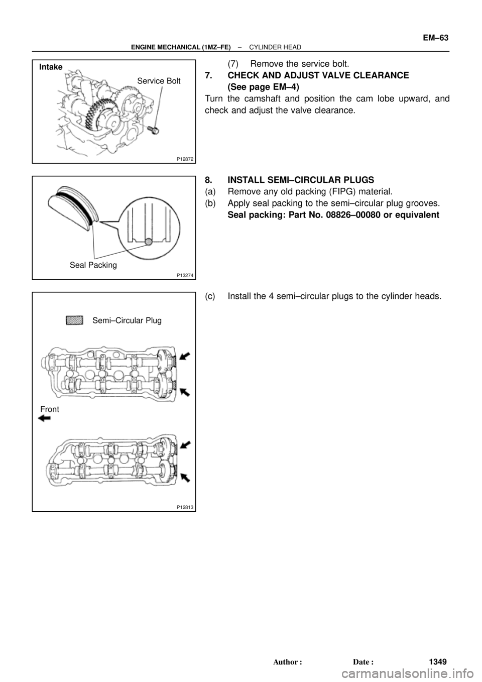
(7) Remove the service bolt.
7. CHECK AND ADJUST VALVE CLEARANCE
(See page EM±4)
Turn the camshaft and position the cam lobe upward, and
check and adjust the valve clearance.
8. INSTALL SEMI±CIRCULAR PLUGS
(a) Remove any old packing (FIPG) material.
(b) Apply seal packing to the semi±circular plug grooves.
Seal packing: Part No. 08826±00080 or equivalent
(c) Install the 4 semi±circular plugs to the cylinder heads.