Page 3571 of 4770
Except California A/T
S04789
Ground
Strap
Inlet PipeRear
Plate
± ENGINE MECHANICAL (1MZ±FE)CYLINDER HEAD
EM±65
1351")
P12710
New O±Ring
A01522
Manifold
Stay California A/T
Manifold Stay
(Except M/T)Except California A/T
S04789
Ground
Strap
Inlet PipeRear
Plate
± ENGINE MECHANICAL (1MZ±FE)CYLINDER HEAD
EM±65
1351 Author�: Date�:
13. INSTALL OIL DIPSTICK AND GUIDE
(a) Install a new O±ring to the dipstick guide.
(b) Apply soapy water to the O±ring.
(c) Push in the dipstick guide end into the guide hole of the
No.1 oil pan.
(d) Install the dipstick guide with the bolt.
Torque: 8 N´m (80 kgf´cm, 69 in.´lbf)
(e) Install the dipstick.
14. INSTALL CAMSHAFT POSITION SENSOR
15. INSTALL LH EXHAUST MANIFOLD
(a) Install a new gasket and the exhaust manifold with the 6
nuts. Uniformly tighten the nuts in several passes.
Torque: 49 N´m (500 kgf´cm, 36 ft´lbf)
(b) Except M/T:
Install the exhaust manifold stay with the bolt and nut. Al-
ternately tighten the bolt and nut.
Torque:
California A/T:
34 N´m (350 kgf´cm, 25 ft´lbf)
Except California A/T:
20 N´m (200 kgf´cm, 15 ft´lbf)
(c) California:
Connect the A/F sensor connector.
(d) Except California:
Connect the heated oxygen sensor (bank 2 sensor 1)
connector.
16. INSTALL WATER INLET PIPE
(a) Install a new O±ring to the water inlet pipe.
(b) Apply soapy water to the O±ring.
(c) Connect the water inlet pipe to the water inlet.
(d) Install the bolt holding the water inlet pipe to the cylinder
head.
Torque: 19.5 N´m (200 kgf´cm, 14 ft´lbf)
17. INSTALL CYLINDER HEAD REAR PLATE
Torque: 8 N´m (80 kgf´cm, 69 in.´lbf)
18. INSTALL ENGINE WIRE PROTECTOR
19. INSTALL NO.3 TIMING BELT COVER
(a) Check that the timing belt cover gaskets have no cracks
or peeling, etc.
If the gaskets have cracks or peeling etc., replace them using
these steps:
�Using a screwdriver and gasket scraper, remove all
the old gasket material.
�Thoroughly clean all components to remove all the
loose material.
Page 3572 of 4770

L = 180 mm (7.09 in.)L = 72 mm (2.83 in.)
L = 335 mm (13.19 in.)L = 180 mm
(7.09 in.)
L = Length Join
LineJoin
Line
Z14262New Gasket
A01808
8
6
5
4
3
2
1
9
10
7
11
EM")
A05194
L = 133 mm (5.24 in.)
L = 180 mm (7.09 in.)L = 72 mm (2.83 in.)
L = 335 mm (13.19 in.)L = 180 mm
(7.09 in.)
L = Length Join
LineJoin
Line
Z14262New Gasket
A01808
8
6
5
4
3
2
1
9
10
7
11
EM±66
± ENGINE MECHANICAL (1MZ±FE)CYLINDER HEAD
1352 Author�: Date�: �
Remove the backing paper from a new gasket and
install the gasket evenly to the part of the timing belt
cover shaded black in the illustration.
NOTICE:
When joining 2 gaskets, do not leave a gap between them.
Cut off any excess gasket.
�After installing the gasket, press down on it so that
the adhesive firmly sticks to the timing belt cover.
(b) Install the timing belt cover with the 6 bolts.
Torque: 8.5 N´m (85 kgf´cm, 74 in.´lbf)
(c) Install the 3 engine wire clamps to the timing belt cover.
20. INSTALL NO.2 IDLER PULLEY (See page EM±21)
21. INSTALL CAMSHAFT TIMING PULLEYS
(See page EM±21)
22. INSTALL TIMING BELT (See page EM±21)
23. INSTALL SPARK PLUGS
24. INSTALL IGNITION COILS
25. INSTALL PS PUMP DRIVE BELT
26. INSTALL GENERATOR DRIVE BELT
(See page SR±28)
27. INSTALL WATER OUTLET
(a) Install 2 new gaskets.
(b) Connect the water outlet to the bypass hose.
(c) Install the water outlet with the 2 bolts, 2 nuts and 2 plate
washers. Alternately tighten the bolts and nuts.
Torque: 15 N´m (150 kgf´cm, 11 ft´lbf)
NOTICE:
Do not scratch the seal surface of the water outlet with the
stud bolt.
(d) Connect the ECT sender gauge connector.
(e) Connect the ECT sensor connector.
(f) Connect the ground strap (connector).
(g) Connect the radiator hose.
(h) Connect the engine coolant reservoir hose.
28. INSTALL INTAKE MANIFOLD ASSEMBLY
(a) Install the intake manifold, delivery pipe and injectors as-
sembly with the 9 bolts, 2 plate washers and 2 nuts. Uni-
formly tighten the bolts and nuts, in several passes, in the
sequence shown.
Torque: 15 N´m (150 kgf´cm, 11 ft´lbf)
Page 3648 of 4770

IG0DB±01
SPARK TEST
CHECK CONNECTION OF IGNITION COIL WITH
CHECK RESISTANCE OF HIGH±TENSION CORDS
CHECK POWER SUPPLY TO IGNITION COILS WITH
1. Turn ignition switch to ON.
2. Check that there is battery positive voltage at ignition
CHECK RESISTANCE OF IGNITION COILS
Resistance:
SecondaryCold Hot
9.7 ± 16.7 kW12.4 ± 19.6 kW
CHECK RESISTANCE OF SENSORS
Resistance: Cold Hot
Camshaft position sensor
Crankshaft position sensor835 ± 1,400 W
985 ± 1,600 W1,060 ± 1,645 W
1,265 ± 1,890 W
CHECK IGT SIGNAL FROM ECM
TRY ANOTHER IGNITERIGNITER CONNECTORS
(See step 2)
Maximum resistance: 25 kW per cord
IGNITERS
coil positive (+) terminal.
(See step 4)
(See steps 5 and 6)
(See page DI±22) NO
OK
OK
OK
OK
OK
BAD
BAD
BAD
BAD
BAD
BAD
Connect securely.
Replace cord(s).
Check wiring between ignition switch to ignition
Replace ignition coil(s) with igniter(s).
Replace sensor(s).
Check wiring between ECM and igniters, and coils with igniters.
then try another ECM.
± IGNITION (5S±FE)IGNITION SYSTEM
IG±1
1683 Author�: Date�:
IGNITION SYSTEM
ON±VEHICLE INSPECTION
NOTICE:
ºColdº and ºHotº in these sentences express the temperature of the coils themselves. ºColdº is from
±10°C (14°F) to 50°C (122°F) and ºHotº is from 50°C (122°F) to 100°C (212°F).
1. INSPECT SPARK TEST
Check that the spark occurs.
(1) Disconnect the high±tension cord from the spark plug.
(2) Remove the spark plug.
(3) Install the spark plug to the high±tension cord.
(4) Ground the spark plug.
(5) See if spark occurs while engine is being cranked.
NOTICE:
To prevent gasoline from being injected from injectors during this test, crank the engine for no more
than 5 ± 10 seconds at time.
If the spark does not occur, do the test as follows:
Page 3651 of 4770
S05528
Ohmmeter
S05310
Ohmmeter IG±4
± IGNITION (5S±FE)IGNITION SYSTEM
1686 Author�: Date�:
If the resistance is not as specified, replace the ignition coil.
(See page IG±6)
(c) Reconnect the high±tension cords to the ignition coils.
(d) Inspect the igniters. (See procedure spark test)
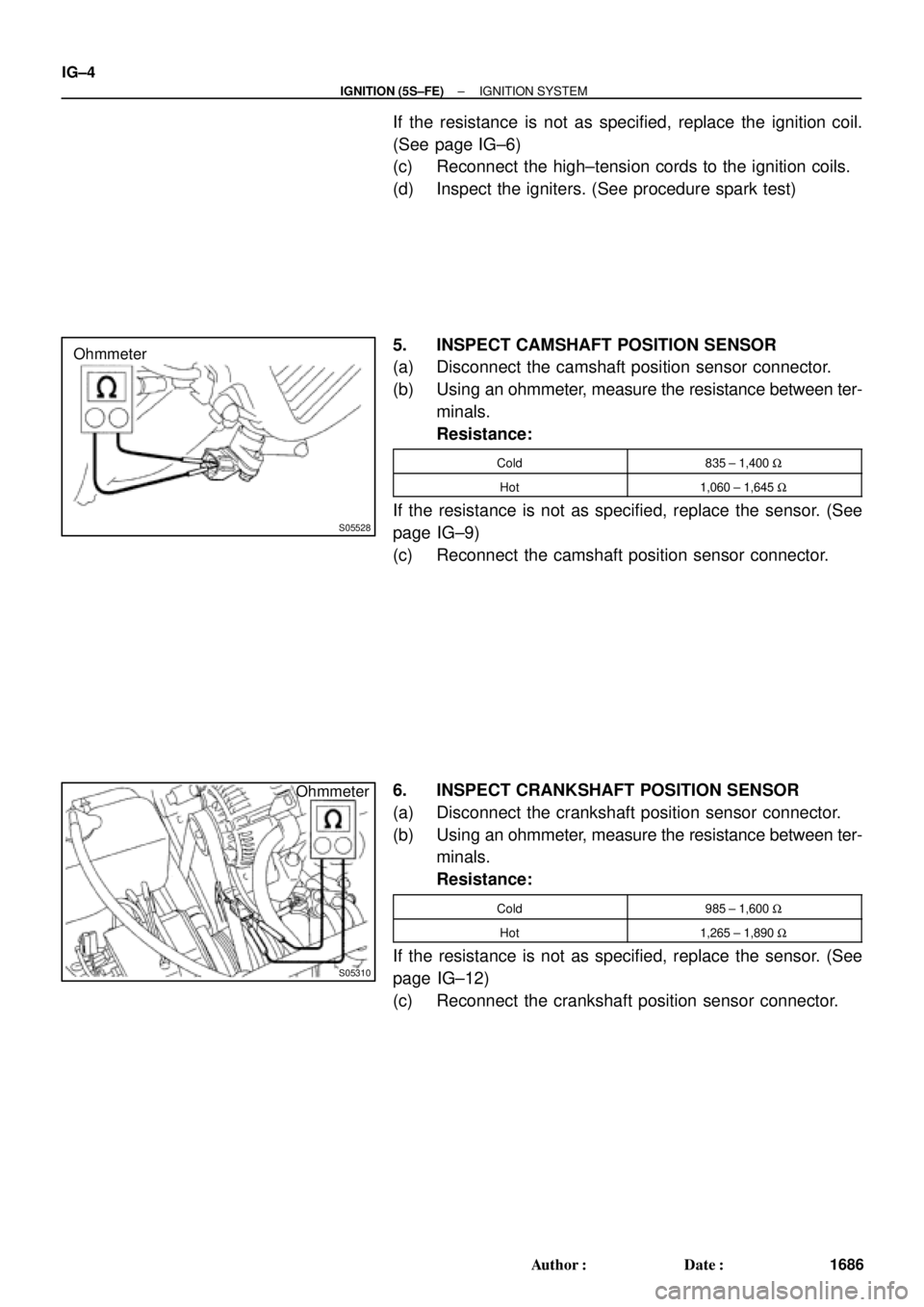
5. INSPECT CAMSHAFT POSITION SENSOR
(a) Disconnect the camshaft position sensor connector.
(b) Using an ohmmeter, measure the resistance between ter-
minals.
Resistance:
Cold835 ± 1,400 W
Hot1,060 ± 1,645 W
If the resistance is not as specified, replace the sensor. (See
page IG±9)
(c) Reconnect the camshaft position sensor connector.
6. INSPECT CRANKSHAFT POSITION SENSOR
(a) Disconnect the crankshaft position sensor connector.
(b) Using an ohmmeter, measure the resistance between ter-
minals.
Resistance:
Cold985 ± 1,600 W
Hot1,265 ± 1,890 W
If the resistance is not as specified, replace the sensor. (See
page IG±12)
(c) Reconnect the crankshaft position sensor connector.
Page 3655 of 4770
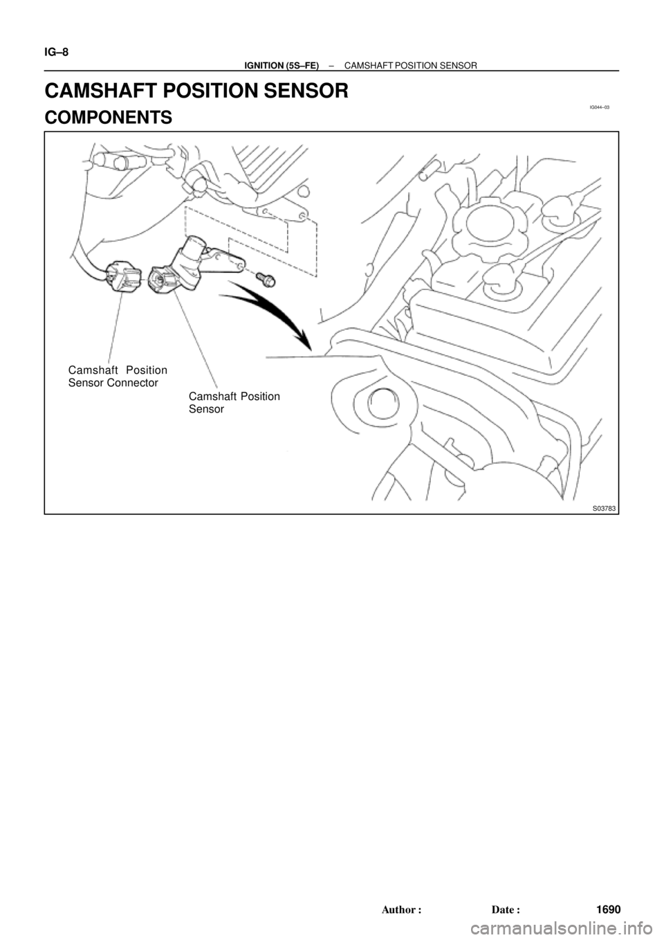
IG044±03
S03783
Camshaft Position
Sensor Connector
Camshaft Position
Sensor IG±8
± IGNITION (5S±FE)CAMSHAFT POSITION SENSOR
1690 Author�: Date�:
CAMSHAFT POSITION SENSOR
COMPONENTS
Page 3656 of 4770
IG0DD±01
± IGNITION (5S±FE)CAMSHAFT POSITION SENSOR
IG±9
1691 Author�: Date�:
REPLACEMENT
1. REMOVE CAMSHAFT POSITION SENSOR
(a) Disconnect the sensor connector.
(b) Remove the bolt and sensor.
2. REINSTALL CAMSHAFT POSITION SENSOR
(a) Install the sensor with the bolt.
Torque: 9.5 N´m (97 kgf´cm, 84 in.´lbf)
(b) Connect the sensor connector.
Page 3660 of 4770

Replace the camshaft position sensor.CHECK RESISTANCE OF CAMSHAFT POSITION SENSOR
Resistance: Cold Hot
835 ± 1,400 W1,060 ± 1,645 W
CHECK IGT SIGNAL FROM ECM
CHECK RESISTANCE OF CRANKSHAFT POSITION SENSOR
Resistance: Cold Hot
1,630 ± 2,740 W2,065 ± 3,225 W
TRY ANOTHER IGNITERReplace the crankshaft position sensor.
Check wiring between ECM and igniter, and
then try another ECM.
OK
OK
OKBAD
BAD
BAD
OK
Continued from the previous page
DENSO made:
Wabash made:1,690 ± 2,560 W2,145 ± 3,010 W
B00848
P24453
WRONG
CORRECT
P24457
IG±2
± IGNITION (1MZ±FE)IGNITION SYSTEM
1696 Author�: Date�:
2. INSPECT HIGH±TENSION CORDS
(a) Remove the V±bank cover.
(b) Disconnect the high±tension cords from the spark plugs.
(1) Using needle±nose pliers, disconnect the cord
clamp from the engine wire protector.
(2) Disconnect the high±tension cords from the spark
plugs.
NOTICE:
Pulling on or bending the cords may damage the conductor
inside.
(3) Disconnect the high±tension cords from the clamp.
(c) Disconnect the high±tension cords from the ignition coils.
(1) Using a screwdriver, lift up the lock claw and discon-
nect the holder from the ignition coils.
(2) Disconnect the high±tension cord at the grommet.
NOTICE:
�Pulling on or bending the cords may damage the con-
ductor inside.
�Do not wipe any of the oil from the grommet after the
high±tension cord is disconnected.
Page 3664 of 4770
IGNITION SYSTEM
1700 Author�: Date�:
(c) Using an ohmmeter, measure the primary coil resistance
between the positive (+) and")
S05622
Ohmmeter
B00849
Ohmmeter
S04599
Ohmmeter IG±6
± IGNITION (1MZ±FE)IGNITION SYSTEM
1700 Author�: Date�:
(c) Using an ohmmeter, measure the primary coil resistance
between the positive (+) and negative (±) terminals.
Primary coil resistance:
Cold0.70 ± 0.94 W
Hot0.85 ± 1.10 W
If the resistance is not as specified, replace the ignition coil.
(d) Using an ohmmeter, measure the secondary coil resis-
tance between the positive (+) and high±tension terminal.
Secondary coil resistance:
AISAN madeCold10.8 ± 14.9 kW
AISAN madeHot13.1 ± 17.5 kW
Diamond madeCold6.8 ± 11.7 kW
Diamond madeHot8.6 ± 13.7 kW
If the resistance is not as specified, replace the ignition coil.
(e) Connect the ignition coil connectors.
(f) Connect the high±tension cords to the ignition coils.
5. INSPECT CAMSHAFT POSITION SENSOR
(a) Disconnect the camshaft position sensor connector.
(b) Using an ohmmeter, measure the resistance between ter-
minals.
Resistance:
DENSO madeCold835 ± 1,400 W
DENSO madeHot1,060 ± 1,645 W
Wabash madeCold1,690 ± 2,560 W
Wabash madeHot2,145 ± 3,010 W
If the resistance is not as specified, replace the camshaft posi-
tion sensor.
(c) Connect the camshaft position sensor connector.