Page 2969 of 4770
F00064
LOCK
1918 17
16
(+)(±) LOCK
1918 17
16
(+)(±)
A6 LOCK
1918 17
16
(+)(±)
± DIAGNOSTICSANTI±LOCK BRAKE SYSTEM (BOSCH Made)
DI±549
784 Author�: Date�:
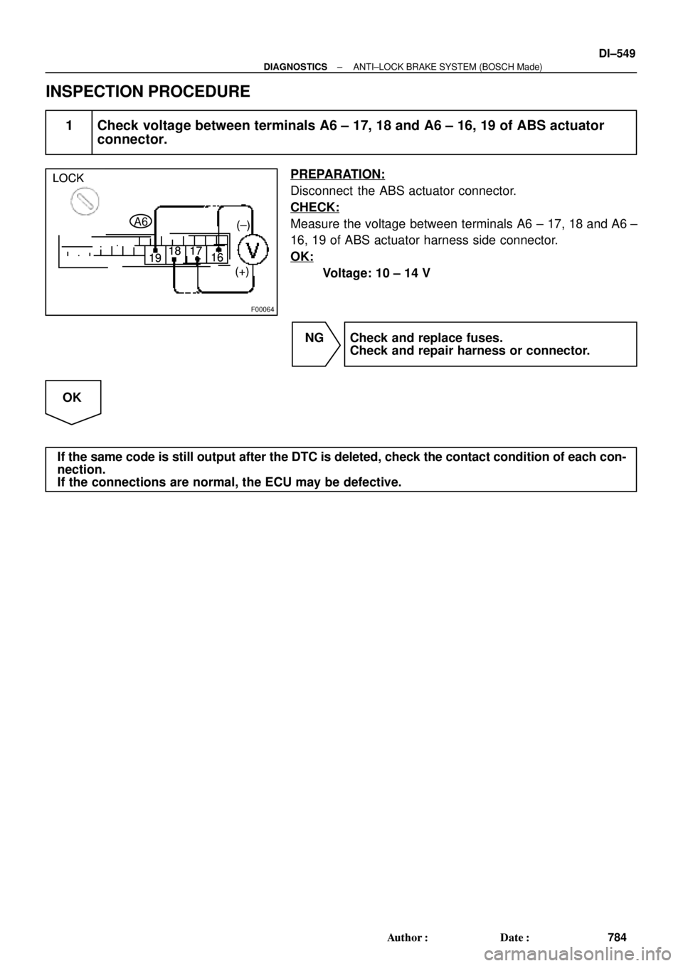
INSPECTION PROCEDURE
1 Check voltage between terminals A6 ± 17, 18 and A6 ± 16, 19 of ABS actuator
connector.
PREPARATION:
Disconnect the ABS actuator connector.
CHECK:
Measure the voltage between terminals A6 ± 17, 18 and A6 ±
16, 19 of ABS actuator harness side connector.
OK:
Voltage: 10 ± 14 V
NG Check and replace fuses.
Check and repair harness or connector.
OK
If the same code is still output after the DTC is deleted, check the contact condition of each con-
nection.
If the connections are normal, the ECU may be defective.
Page 2970 of 4770
F03949
Actuator Assembly
BatteryActuator Assembly
MAINB±GF4 1 ALT
FL
Block 1F5 B±G3
ABS
12 3
Engine
Room R/B
No.3L
L
18
A6
+B+BA6
Valve Relay
Motor Relay17
A6 16 GND2
W±BEA
W±B
W±B 19
A6GND1 ECU DI±550
± DIAGNOSTICSANTI±LOCK BRAKE SYSTEM (BOSCH Made)
785 Author�: Date�:
DTC 21, 22, 23, 24 ABS Solenoid Valve Circuit
CIRCUIT DESCRIPTION
This solenoid goes on when signals are received from the ECU and controls the pressure acting on the wheel
cylinders thus controlling the braking force.
DTC No.DTC Detecting ConditionTrouble Area
21, 22, 23, 24Solenoid valve signal does not match to the check result.�Each solenoid valve
Fail safe function:
If trouble occurs in the actuator solenoid valve circuit, the ECU cuts off current to the ABS solenoid valve
relay and prohibits ABS control.
WIRING DIAGRAM
DI042±08
Page 2978 of 4770

F03950
Actuator Assembly LB±R
IG1Actuator Assembly LB±R
IG1Actuator Assembly LB±R
IG1Actuator Assembly LB±R
IG1Actuator Assembly L
IG1
BatteryMAINB±G1
F4 ALTFL
Block 1F5 B±G3
ABS
12
Engine
Room R/B
No.3 3L
18
A617
A6
+B+B
Valve Relay
Motor Relay
GND2
A6
1615
A65
B±R
IK3B±R
C
C
J12 J/C
ECU
GND119
A6W±B
W±B
W±B
EAECU±IG
Instrument
Panel J/B 1J
9 DI±558
± DIAGNOSTICSANTI±LOCK BRAKE SYSTEM (BOSCH Made)
793 Author�: Date�:
DTC 41 Power Source Circuit
CIRCUIT DESCRIPTION
This is the power source for the ECU, hence the actuators.
DTC No.DTC Detecting ConditionTrouble Area
41
Vehicle speed at about 6 km/h (4 mph), low battery voltage
is less than 9.4 V at the time of non±operation of ABS
control or less than 8.8 V at the time of operation of ABS
control, and high battery voltage is more than 17.4 V.�Battery
�Charging system
�Power source circuit
�ECU
Fail safe function:
If trouble occurs in the power source circuit, the ECU cuts off current to the ABS solenoid valve relay and
prohibits ABS control.
WIRING DIAGRAM
DI045±08
Page 2980 of 4770
F00067
IG1
GND ON
(+) (±) IG1
GND ON
(+) (±) IG1
GND ON
(+) (±)IG1
GND ON
(+) (±)
F00068
LOCK
GND (+)
(±) LOCK
GND (+)
(±) LOCK
GND (+)
(±)LOCK
GND (+)
(±)
DI±560
± DIAGNOSTICSANTI±LOCK BRAKE SYSTEM (BOSCH Made)
795 Author�: Date�:
3 Check voltage between terminals IG1 and GND of ABS actuator connector.
PREPARATION:
Disconnect ABS actuator connector.
CHECK:
(a) Turn the ignition switch ON.
(b) Measure voltage between terminals IG1 and GND of ABS
actuator harness side connector.
OK:
Voltage: 10 ± 14 V
OK Check and replace ABS ECU.
NG
4 Check continuity between terminals GND of ABS actuator connector and body
ground.
CHECK:
Measure resistance between terminal GND of ABS actuator
harness side connector and body ground.
OK:
Resistance: 1 W or less
NG Repair or replace harness or connector.
OK
Check for open circuit in harness and connector between ABS ECU and ECU±IG
(See page IN±31).
Page 2982 of 4770
F00069
STP (+) (±)
DI±562
± DIAGNOSTICSANTI±LOCK BRAKE SYSTEM (BOSCH Made)
797 Author�: Date�:
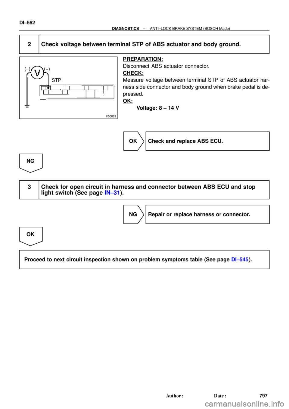
2 Check voltage between terminal STP of ABS actuator and body ground.
PREPARATION:
Disconnect ABS actuator connector.
CHECK:
Measure voltage between terminal STP of ABS actuator har-
ness side connector and body ground when brake pedal is de-
pressed.
OK:
Voltage: 8 ± 14 V
OK Check and replace ABS ECU.
NG
3 Check for open circuit in harness and connector between ABS ECU and stop
light switch (See page IN±31).
NG Repair or replace harness or connector.
OK
Proceed to next circuit inspection shown on problem symptoms table (See page DI±545).
Page 2984 of 4770
F00067
ON
IG1
(+) (±)
GND
DI±564
± DIAGNOSTICSANTI±LOCK BRAKE SYSTEM (BOSCH Made)
799 Author�: Date�:
4 Check voltage between terminals IG1 and GND of ABS actuator connector.
PREPARATION:
Disconnect ABS actuator connector.
CHECK:
(a) Turn the ignition switch ON.
(b) Measure voltage between terminals IG1 and GND of ABS
actuator harness side connector.
OK:
Voltage: 10 ± 14 V
NG Check for open and short circuit in harness and
connector between ECU±IG fuse and ABS ac-
tuator (See page IN±31).
OK
5 Check connection of ABS actuator connector.
CHECK:
Check the connection of the ABS actuator connector and check the ABS warning light goes off.
OK Repair or replace harness or connector.
NG
Check and replace ABS ECU.
Page 2991 of 4770
F00072
± DIAGNOSTICSANTI±LOCK BRAKE SYSTEM (BOSCH Made)
DI±571
806 Author�: Date�:
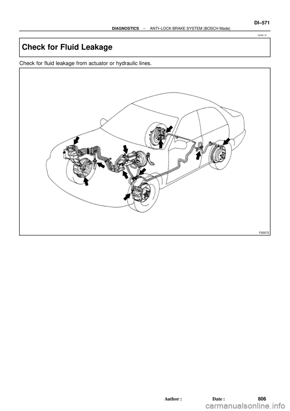
Check for Fluid Leakage
Check for fluid leakage from actuator or hydraulic lines.
DI04B±10
Page 2998 of 4770

DI04F±04
DI±578
± DIAGNOSTICSABS & TRACTION CONTROL SYSTEM
813 Author�: Date�:
DIAGNOSTIC TROUBLE CODE CHART
HINT:
�Using SST 09843 ±18020, connect the terminals Tc and E1.
�If a malfunction code is displayed during the DTC check, check the circuit listed for the code. For details
of each code, turn to the page referred to under the ºSee pageº for respective ºDTC No.º in the DTC
chart.
DTC No.
(See Page)Detection ItemTrouble Area
11
(DI±584)Open circuit in ABS & TRAC solenoid relay circuit�ABS & TRAC solenoid relay
ABS & TRAC l id l i it12
(DI±584)Short circuit in ABS & TRAC solenoid relay circuit
�ABS & TRAC solenoid relay circuit
�ECU
13
(DI±587)Open circuit in ABS & TRAC motor relay circuit�ABS & TRAC motor relay
ABS & TRAC t l i it14
(DI±587)Short circuit in ABS & TRAC motor relay circuit
�ABS & TRAC motor relay circuit
�ECU
21
(DI±590)Open or short circuit in right front solenoid circuit
�ABS & TRAC actuator
�SFRR or SFRH circuit
�ECU
22
(DI±590)Open or short circuit in left front solenoid circuit
�ABS & TRAC actuator
�SFLR or SFLH circuit
�ECU
23
(DI±590)Open or short circuit in right rear solenoid circuit
�ABS & TRAC actuator
�SRRR or SRRH circuit
�ECU
24
(DI±590)Open or short circuit in left rear solenoid circuit
�ABS & TRAC actuator
�SRLR or SRLH circuit
�ECU
25
(DI±590)Open or short circuit in SMC1 circuit
�ABS & TRAC actuator
�SMC1 circuit
�ECU
26
(DI±590)Open or short circuit in SMC2 circuit
�ABS & TRAC actuator
�SMC2 circuit
�ECU
27
(DI±590)Open or short circuit in SRC1 circuit
�ABS & TRAC actuator
�SRC1 circuit
�ECU
28
(DI±590)Open or short circuit in SRC2 circuit
�ABS & TRAC actuator
�SRC2 circuit
�ECU
31
(DI±593)Right front wheel speed sensor signal malfunction
32
(DI±593)Left front wheel speed sensor signal malfunction�Right front, left front, right rear and left rear speed sensor
�Each speed sensor circuit
33
(DI±593)Right rear wheel speed sensor signal malfunction
�Each s eed sensor circuit
�Speed sensor rotor
�ECU
34
(DI±593)Left rear wheel speed sensor signal malfunction
41
(DI±598)Low battery positive voltage or abnormally high battery
positive voltage
�Battery
�Charging system
�Power source circuit
�ECU

 (±) IG1
GND ON
(+) (±) IG1
GND ON
(+) (±)IG1
GND ON
(+) (±)
F00068
LOCK
GND (+)
(±) LOCK
GND (+)
(±) LOCK
GND (+)
(±)LOCK
GND (+)
(±)
DI±560
± DIAGNOSTICSANTI±LOCK BRA")