Page 3318 of 4770
I00285
Cruise Control ECU
2
STP±
8
L
J27
J/C
G±W A A
G±W 5
1R
1R
G±W 1
4 Stop Light Switch
2
3
W
7
1C4
1BG±B 4
B±R
FL BLOCK
F91 1
F4
B±G
FL MAIN
BatteryR±Y
Cruise Control
Actuator
3
4 J/C
A
J7 A
J7
W±B
1J
1JJ/C
AJ11
W±B
IG Instrument Panel J/B
STOP
ALT
C15
C15
Instrument Panel J/B
Instrument Panel J/BW±B
87 DI±898
± DIAGNOSTICSCRUISE CONTROL SYSTEM
1133 Author�: Date�:
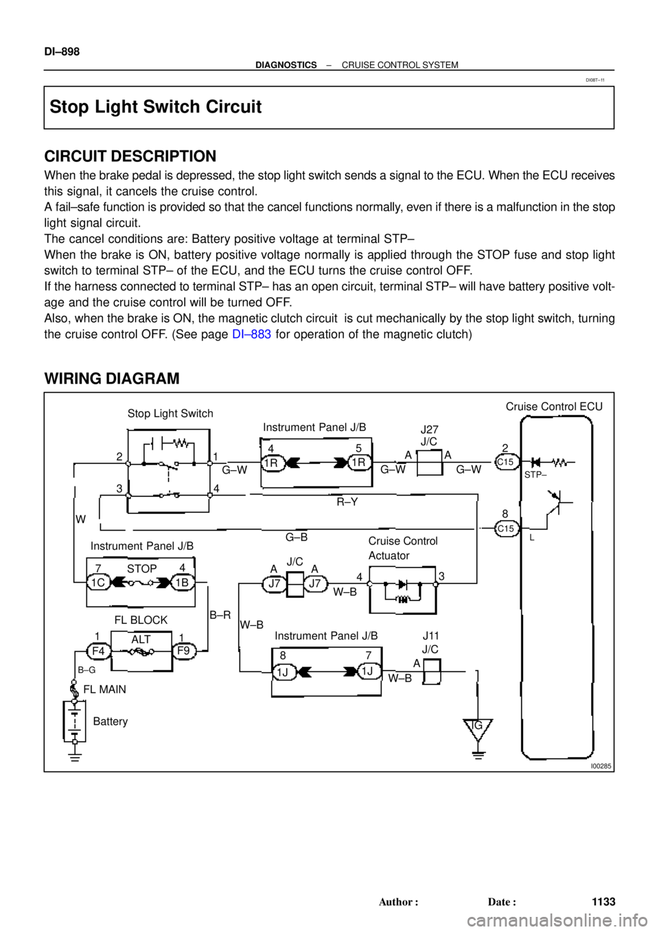
Stop Light Switch Circuit
CIRCUIT DESCRIPTION
When the brake pedal is depressed, the stop light switch sends a signal to the ECU. When the ECU receives
this signal, it cancels the cruise control.
A fail±safe function is provided so that the cancel functions normally, even if there is a malfunction in the stop
light signal circuit.
The cancel conditions are: Battery positive voltage at terminal STP±
When the brake is ON, battery positive voltage normally is applied through the STOP fuse and stop light
switch to terminal STP± of the ECU, and the ECU turns the cruise control OFF.
If the harness connected to terminal STP± has an open circuit, terminal STP± will have battery positive volt-
age and the cruise control will be turned OFF.
Also, when the brake is ON, the magnetic clutch circuit is cut mechanically by the stop light switch, turning
the cruise control OFF. (See page DI±883 for operation of the magnetic clutch)
WIRING DIAGRAM
DI08T±11
Page 3329 of 4770
I08434
Instrument Panel J/B
Ignition Switch
ECU±IG
B 9 J12
J/C
B±YC15
B±R C
C
GND
IG1
2
B±R IG1
Battery24
AM1
Instrument Panel J/B
AM1 1K1
W
B±GF9
F41
W±B
FL MAINCruise Control ECU
1J9
B±R
1K
1B1
16
C15
W±B
W±BJ8A
J7AJ/C
1J8
1J7Instrument Panel J/B
A J11
J/C FL BLOCK
ALT
± DIAGNOSTICSCRUISE CONTROL SYSTEM
DI±909
1144 Author�: Date�:
ECU Power Source Circuit
CIRCUIT DESCRIPTION
The ECU power source supplies power to the actuator and sensors, etc, when terminal GND and the cruise
control ECU case are grounded.
WIRING DIAGRAM
DI08X±11
Page 3338 of 4770
DI±918
± DIAGNOSTICSCRUISE CONTROL SYSTEM
1153 Author�: Date�:
Actuator Control Cable
INSPECTION PROCEDURE
1 Actuator control cable inspection
OK:
(a) Check that the actuator and control cable throttle link are properly installed and that the cable and link
are connected correctly.
(b) Check that the actuator and bell crank operate smoothly.
(c) Check that the cable is not loose or too tight.
OK:
Freeplay: less than 10 mm
HINT:
�If the control cable is very loose, the vehicle's loss of speed going uphill will be large.
�If the control cable is too tight, the idle RPM will become high.
DI092±07
Page 3456 of 4770
EM0YV±01
A02195
Radiator Reservoir Hose
Generator Drive BeltUpper Radiator
Hose
Support BracketFront Exhaust Pipe PS Oil Pressure Switch
ConnectorBattery TrayBattery
PS Pump Drive Belt
PS Pump
Support Stay Upper Radiator Support
Lower Radiator Hose
A/C Compressor
Cylinder Block Insulator
LH Front Fender Apron Seal
Oil Cooler Hose (A/T)
Cruise Control ActuatorEVAP Hose
Air Filter Upper Radiator
Support
EVAP Hose Hood
PCV Hose
Support
Bracket � Gasket
�
� Non±reusable part� Gasket
�Clamp
N´m (kgf´cm, ft´lbf)
62 (630, 46)
56 (570, 41)
�
: Specified torque
Washer Hose
for Windshield
No.1 Electric
Cooling Fan
Connector
ECT Switch
Connector No.2 Electric
Cooling Fan
ConnectorRadiator
Assembly
A/C Compressor
ConnectorLower Radiator
Support
RH Front Fender
Aplon Seal
Cruise
Control
Actuator
Connector
Battery
Hold±Down
ClampAir Cleaner
Case
VSV
Connector
for EVAP
EVAP
Hose
IAT Sensor
Connector
Air
Cleaner
Cap
EM±64
± ENGINE MECHANICAL (5S±FE)ENGINE UNIT
1236 Author�: Date�:
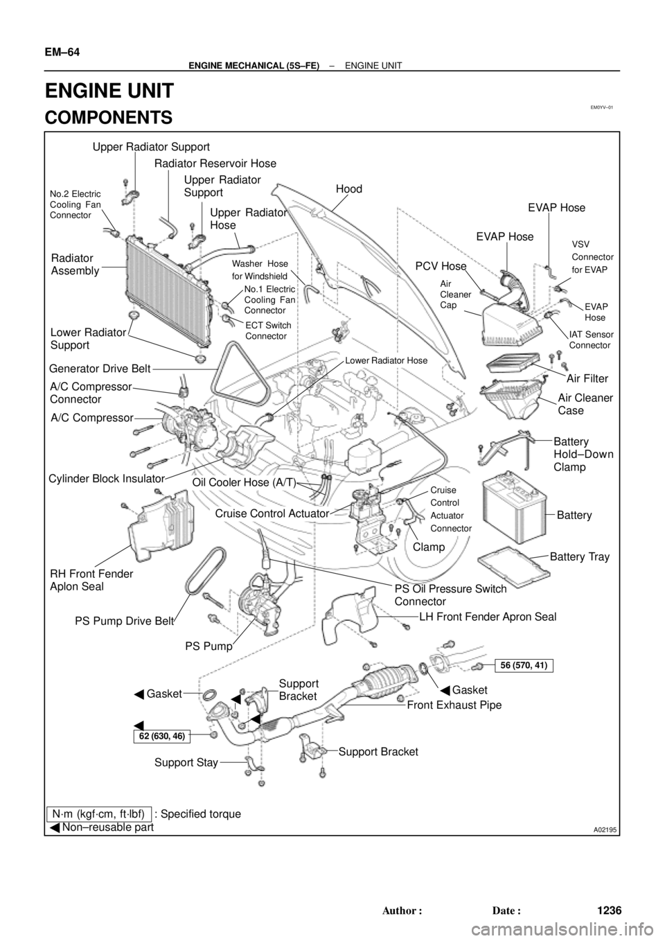
ENGINE UNIT
COMPONENTS
Page 3461 of 4770
EM08F±04
S05251
± ENGINE MECHANICAL (5S±FE)ENGINE UNIT
EM±69
1241 Author�: Date�:
REMOVAL
1. REMOVE HOOD
2. REMOVE FRONT FENDER APRON SEALS
3. DRAIN ENGINE COOLANT
4. DRAIN ENGINE OIL
5. DISCONNECT ACCELERATOR CABLE
6. REMOVE AIR CLEANER CAP
(a) Disconnect the IAT sensor connector.
(b) Disconnect the VSV connector for the EVAP
(c) Disconnect the PCV hose from the cylinder head cover.
(d) Disconnect the EVAP hose from the throttle body.
(e) Disconnect the EVAP hose from the VSV.
(f) Disconnect the 2 clamps, and disconnect the air cleaner
cap from the air cleaner case.
(g) Loosen hose clamp, and disconnect the air cleaner hose
from the throttle body.
(h) Remove the air cleaner cap and hose assembly.
7. REMOVE AIR CLEANER CASE
(a) Remove the air filter.
(b) Remove the 3 bolts and air cleaner case.
8. REMOVE BATTERY AND TRAY
9. REMOVE CRUISE CONTROL ACTUATOR
10. REMOVE RADIATOR (See page CO±18)
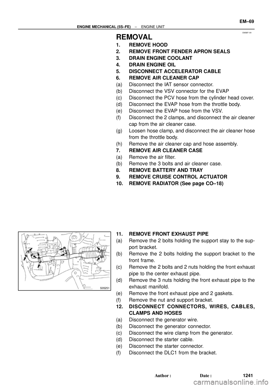
11. REMOVE FRONT EXHAUST PIPE
(a) Remove the 2 bolts holding the support stay to the sup-
port bracket.
(b) Remove the 2 bolts holding the support bracket to the
front frame.
(c) Remove the 2 bolts and 2 nuts holding the front exhaust
pipe to the center exhaust pipe.
(d) Remove the 3 nuts holding the front exhaust pipe to the
exhaust manifold.
(e) Remove the front exhaust pipe and 2 gaskets.
(f) Remove the nut and support bracket.
12. DISCONNECT CONNECTORS, WIRES, CABLES,
CLAMPS AND HOSES
(a) Disconnect the generator wire.
(b) Disconnect the generator connector.
(c) Disconnect the wire clamp from the generator.
(d) Disconnect the starter cable.
(e) Disconnect the starter connector.
(f) Disconnect the DLC1 from the bracket.
Page 3472 of 4770
S05251
EM±80
± ENGINE MECHANICAL (5S±FE)ENGINE UNIT
1252 Author�: Date�:
(b) Connect the generator connector.
(c) Install the wire clamp to the generator.
(d) Connect the starter cable.
(e) Connect the starter connector.
(f) Install the DLC1 to the bracket.
(g) Install the engine wire clamp to the bracket on the RH
fender apron.
(h) Connect the MAP sensor connector.
(i) Install the wire clamp to the bracket for the MAP sensor.
(j) Connect the VSV connector for the vapor pressure sen-
sor.
(k) Connect the 2 ground strap connectors to the RH fender
apron.
(l) Connect the 2 ground strap connectors to the LH fender
apron.
(m) Install the engine wire protector clamp to the battery
bracket.
(n) Install the engine wire to the clamp on the fuel filter.
(o) Connect the ground cable to the transaxle.
(p) Connect the brake booster vacuum hose to the intake
manifold.
(q) Connect the heater hose to the water outlet.
(r) Connect the heater hose to the water bypass pipe.
(s) Connect the fuel inlet hose to the fuel filter with 2 new gas-
kets and the union bolt.
Torque: 29 N´m (300 kgf´cm, 21 ft´lbf)
(t) Connect the MAP sensor vacuum hose to the gas filter on
the intake manifold.
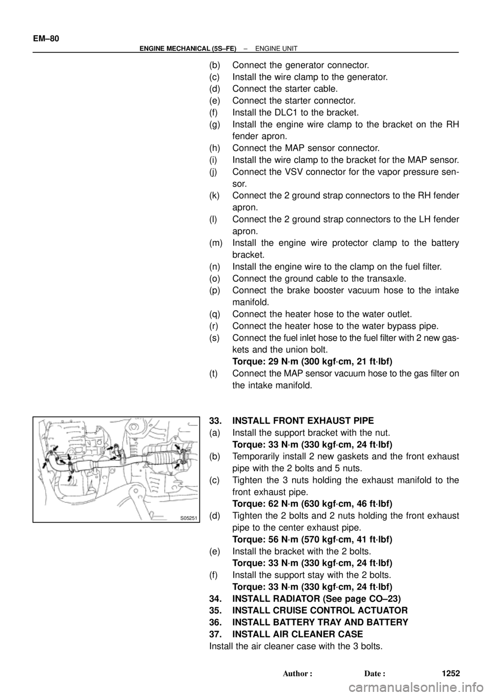
33. INSTALL FRONT EXHAUST PIPE
(a) Install the support bracket with the nut.
Torque: 33 N´m (330 kgf´cm, 24 ft´lbf)
(b) Temporarily install 2 new gaskets and the front exhaust
pipe with the 2 bolts and 5 nuts.
(c) Tighten the 3 nuts holding the exhaust manifold to the
front exhaust pipe.
Torque: 62 N´m (630 kgf´cm, 46 ft´lbf)
(d) Tighten the 2 bolts and 2 nuts holding the front exhaust
pipe to the center exhaust pipe.
Torque: 56 N´m (570 kgf´cm, 41 ft´lbf)
(e) Install the bracket with the 2 bolts.
Torque: 33 N´m (330 kgf´cm, 24 ft´lbf)
(f) Install the support stay with the 2 bolts.
Torque: 33 N´m (330 kgf´cm, 24 ft´lbf)
34. INSTALL RADIATOR (See page CO±23)
35. INSTALL CRUISE CONTROL ACTUATOR
36. INSTALL BATTERY TRAY AND BATTERY
37. INSTALL AIR CLEANER CASE
Install the air cleaner case with the 3 bolts.
Page 3575 of 4770
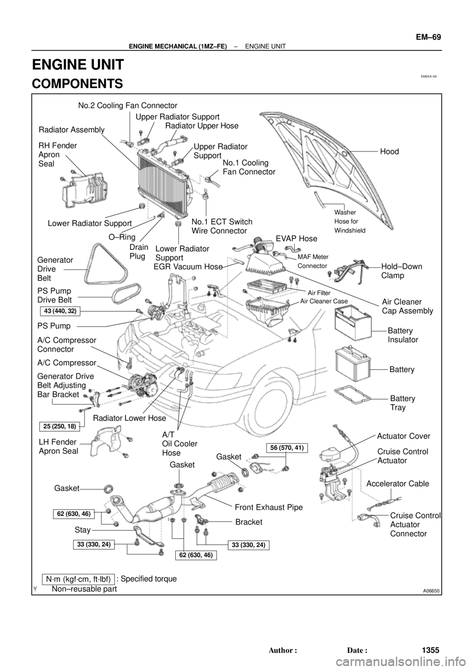
EM04X±04
A06650
No.2 Cooling Fan Connector
Upper Radiator Support
Radiator Assembly
RH Fender
Apron
Seal
Generator
Drive
Belt
A/C Compressor
ConnectorNo.1 ECT Switch
Wire Connector
Battery
Insulator
Battery
Battery
Tray Generator Drive
Belt Adjusting
Bar Bracket
LH Fender
Apron SealA/T
Oil Cooler
Hose
� Gasket A/C Compressor
43 (440, 32)
25 (250, 18)
�Non±reusable partStay
N´m (kgf´cm, ft´lbf)Bracket Front Exhaust Pipe: Specified torque� Gasket
62 (630, 46)
33 (330, 24)
�
62 (630, 46)
33 (330, 24)
� Gasket
56 (570, 41)
Actuator Cover
EGR Vacuum HoseUpper Radiator
Support
No.1 Cooling
Fan ConnectorHood
Hold±Down
Clamp
Washer
Hose for
Windshield
Air Filter
Air Cleaner Case
� O±Ring Lower Radiator Support
Drain
Plug
Lower Radiator
Support
Air Cleaner
Cap Assembly
Radiator Upper Hose
Cruise Control
Actuator
Cruise Control
Actuator
Connector
Accelerator Cable
PS Pump
Radiator Lower Hose
� PS Pump
Drive Belt
EVAP Hose
MAF Meter
Connector
± ENGINE MECHANICAL (1MZ±FE)ENGINE UNIT
EM±69
1355 Author�: Date�:
ENGINE UNIT
COMPONENTS
Page 3577 of 4770

EM04Y±03
S05048
± ENGINE MECHANICAL (1MZ±FE)ENGINE UNIT
EM±71
1357 Author�: Date�:
REMOVAL
1. REMOVE BATTERY AND TRAY
2. REMOVE HOOD
3. REMOVE ENGINE FENDER APRON SEALS
4. DRAIN ENGINE COOLANT
5. DRAIN ENGINE OIL
6. DISCONNECT ACCELERATOR CABLE
7. REMOVE AIR CLEANER CAP ASSEMBLY AND AIR
CLEANER CASE
8. REMOVE CRUISE CONTROL ACTUATOR
9. REMOVE RADIATOR (See page CO±18)
10. REMOVE FRONT EXHAUST PIPE
(a) Remove the 2 bolts holding the support stay to the sup-
port bracket.
(b) Remove the 2 bolts holding the support bracket to the
front frame.
(c) Remove the 2 bolts and 2 nuts holding the front exhaust
pipe to the center exhaust pipe.
(d) Remove the 4 nuts holding the front exhaust pipe to the
exhaust manifolds.
(e) Remove the front exhaust pipe and 3 gaskets.
11. DISCONNECT CONNECTORS, CABLE, CLAMPS
AND HOSES
(a) Disconnect the igniter connector on the LH fender apron.
(b) Disconnect the noise filter connector on the LH fender
apron.
(c) Disconnect the generator wire and connector.
(d) Disconnect the starter wire and connector.
(e) Disconnect the 2 ground strap connectors from the LH
fender apron.
(f) Disconnect the 2 ground strap connectors from the RH
fender apron.
(g) Disconnect the ground cable from the battery body brack-
et.
(h) Disconnect the engine wire protector clamp from the bat-
tery body bracket.
(i) Disconnect the engine wire clamp from the bracket on the
RH fender apron.
(j) Disconnect the engine wire clamp from the bracket on the
fuel filter.