Page 3012 of 4770
DI±592
± DIAGNOSTICSABS & TRACTION CONTROL SYSTEM
827 Author�: Date�:
2 Check for open and short circuit in harness and connector between ABS &
TRAC ECU and actuator (See page IN±31).
NG Repair or replace harness or connector.
OK
If the same code is still output after the DTC is deleted, check the contact condition of each con-
nection.
If the connections are normal, the ECU may be defective.
Page 3018 of 4770

F00175
Battery MAIN FL Block
B±G 1K2Ignition
Switch
Instrument Panel J/B
1B
F4 F91A16
GND3
B±R
1Instrument Panel J/B
1
A15 B±YJ/C
4B±R
CABS & TRAC ECU
9
A17 1JJ12
IG1
W±B W
GND1
GND2 21K1
CB±R
A17 W±B
W±B
EA8
15
109
W±B
W±B
Battery MAIN FL Block
B±G 1K2Ignition
Switch
Instrument Panel J/B
1B
F4 F91A16
GND3
B±R
1Instrument Panel J/B
1
A15 B±YJ/C
4B±R
CABS & TRAC ECU
9
A17 1JJ12
IG1
W±B W
GND1
GND2 21K1
CB±R
A17 W±B
W±B
EA8
15
109
W±B
W±B
Battery MAIN FL Block
B±G 1K2Ignition
Switch
Instrument Panel J/B
1B
F4 F91A16
GND3
B±R
1Instrument Panel J/B
1
A15 B±YJ/C
4B±R
CABS & TRAC ECU
9
A17 1JJ12
IG1
W±B W
GND1
GND2 21K1
CB±R
A17 W±B
W±B
EA8
15
109
W±B
W±B
Battery MAIN FL Block
B±G 1K2Ignition
Switch
Instrument Panel J/B
1B
F4 F91A16
GND3
B±R
1Instrument Panel J/B
1
A15 B±YJ/C
4B±R
CABS & TRAC ECU
9
A17 1JJ12
IG1
W±B W
GND1
GND2 21K1
CB±R
A17 W±B
W±B
EA8
15
109
W±B
W±BBattery MAIN FL Block
ALT
B±GAM1 1K2Ignition
Switch
Instrument Panel J/B
1B
F4 F91A16
GND3
B±R
1Instrument Panel J/B
1
A15 B±YJ/C
ECU±IG 4B±R
CABS & TRAC ECU
9
A17 1JJ12
IG1
W±B W
GND1
GND2 21K1
CB±R
A17 W±B
W±B
EA8
15
109
W±B
W±B DI±598
± DIAGNOSTICSABS & TRACTION CONTROL SYSTEM
833 Author�: Date�:
DTC 41 IG Power Source Circuit
CIRCUIT DESCRIPTION
This is the power source for the ECU, hence the actuators.
DTC No.DTC Detecting ConditionTrouble Area
41
Detection of any conditions from 1. through 3.:
1. Vehicle speed is 3 km/h (1.9 mph) or more and battery
voltage is less than 9.5 V continues for 10 sec. or more.
2. Battery voltage has never exceeded more than 17.0 V
and has become less than 9.5 V within 2.16 sec., under
malfunction of solenoid relay monitor after the solenoid
relay is ON, at ECU AST terminal voltage of ECU has
become 8.0 V or more or under malfunction of motor
relay monitor and after the motor relay is ON, motor
relay monitor has become ON.
3. Battery voltage is more than 17.0 V , which continues for
1.2 sec. or more or battery voltage has become more
than 17.0 V within 2.16 sec. and solenoid or motor relay
monitor is under malfunction condition.
�Battery
�Charging system
�Power source circuit
�ECU
Fail safe function:
If any trouble occurs in the power source circuit, the ECU cuts off current to the ABS & TRAC solenoid relay
and prohibits ABS control and TRAC control.
WIRING DIAGRAM
DI04N±04
Page 3026 of 4770
F03413
ALTEngine Room R/B No. 3
2ABS & TRAC
Motor Relay
A8ABS & TRAC ActuatorABS
4
W±R
MTR+ GR±L
14 24
MR A15
13
F5
F4
B±GFL
Block
MAIN
Battery
EA 1 B±G
333
1
2
3
A8A8
1 23
W±BA15
A15 GR±R
R±W 1ABS & TRAC ECU
1 DI±606
± DIAGNOSTICSABS & TRACTION CONTROL SYSTEM
841 Author�: Date�:
DTC 51 ABS Pump Motor Lock
CIRCUIT DESCRIPTION
DTC No.DTC Detecting ConditionTrouble Area
51
In the midst of initial check, after the current flows to the
motor for 3 sec. and motor relay is turned OFF , then
within 0.66 sec., the condition that the motor relay
monitor is OFF continues for 0.24 sec. or more.
�ABS pump motor
Fail safe function:
If any trouble occurs in the ABS & TRAC pump motor, the ECU cuts off current to the ABS & TRAC solenoid
relay and prohibits ABS control and TRAC control.
WIRING DIAGRAM
DI4KX±01
Page 3027 of 4770
F03291
(±)
(+)12A8
± DIAGNOSTICSABS & TRACTION CONTROL SYSTEM
DI±607
842 Author�: Date�:
INSPECTION PROCEDURE
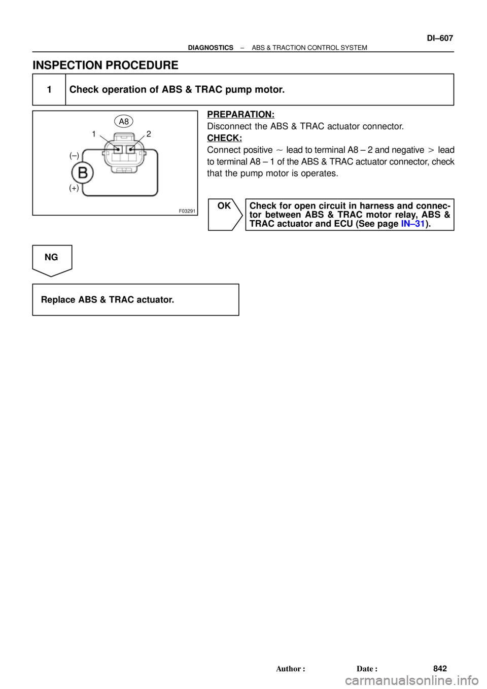
1 Check operation of ABS & TRAC pump motor.
PREPARATION:
Disconnect the ABS & TRAC actuator connector.
CHECK:
Connect positive � lead to terminal A8 ± 2 and negative � lead
to terminal A8 ± 1 of the ABS & TRAC actuator connector, check
that the pump motor is operates.
OK Check for open circuit in harness and connec-
tor between ABS & TRAC motor relay, ABS &
TRAC actuator and ECU (See page IN±31).
NG
Replace ABS & TRAC actuator.
Page 3032 of 4770

F00168
BatteryABS & TRAC
Solenoid Relay Engine Room R/B No. 3
3ABS & TRAC
ECU
A8 1
R±L
C 5 4
IG3 IK2 6
J/C C10
EA4ABS Warning Light 8
12 II3
G±B23 2
22 ABS & TRAC
Actuator
DLC1 Short
Pin
WA
J29 33 3 3
3
W±B4
ABS & TRAC
ECUR±L
4
R±L
II3 5
G±B
C C G±B R±LC107
ABS & TRAC ECU R±LR±L
J/C
D 1D
GAUGE Instrument Panel J/B
A16 J4 D
G±B4 W±L
2
DI±612
± DIAGNOSTICSABS & TRACTION CONTROL SYSTEM
847 Author�: Date�:
ABS Warning Light Circuit
CIRCUIT DESCRIPTION
If the ECU detects a trouble, it lights the ABS warning light while at the same time prohibiting ABS control.
At this time, the ECU records a DTC in memory.
Connect terminals Tc and E
1 of the DLC1 or DLC2 to make the ABS warning light blink and output the DTC.
WIRING DIAGRAM
INSPECTION PROCEDURE
Troubleshoot in accordance with the chart below for each trouble symptom.
ABS warning light does not light upGo to step 1
ABS warning light remains onGo to step 3
1 Check ABS warning light.
See combination meter troubleshooting on page BE±2.
NG Repair bulb or combination meter assembly.
OK
DI04V±04
Page 3043 of 4770
F00070
± DIAGNOSTICSABS & TRACTION CONTROL SYSTEM
DI±623
858 Author�: Date�:
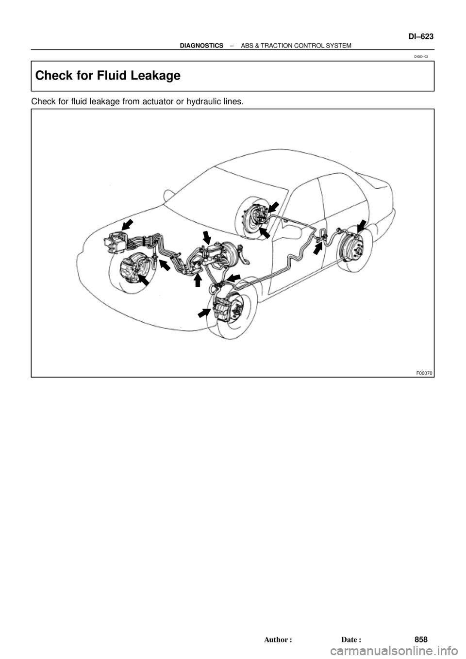
Check for Fluid Leakage
Check for fluid leakage from actuator or hydraulic lines.
DI050±03
Page 3295 of 4770

DI08I±08
± DIAGNOSTICSCRUISE CONTROL SYSTEM
DI±875
111 0 Author�: Date�:
DIAGNOSTIC TROUBLE CODE CHART
If a malfunction code is displayed during the DTC check, check the circuit listed for that code in the table
below and proceed to the appropriate page.
DTC No.
(See Page)Circuit InspectionTrouble Area
11, 15
(DI±881)Actuator Motor Circuit
�Actuator motor
�Harness or connector between cruise control ECU and
actuator motor
�Cruise control ECU
12
(DI±883)Actuator Magnetic Clutch Circuit
�STOP Fuse
�Stop light switch
�Actuator magnetic clutch
�Harness or connector between cruise control ECU and
actuator magnetic clutch, actuator magnetic clutch and body
ground
�Cruise control ECU
14
(DI±886)Actuator Mechanical Malfunction�Actuator motor (actuator lock: motor, arm)
�Cruise control ECU
21
(DI±888)Open in Vehicle Speed Sensor Circuit
�Combination meter
�Harness or connector between cruise control ECU and com-
bination meter, combination meter and vehicle speed sensor
�Vehicle speed sensor
�Cruise control ECU
23
(DI±891)Vehicle Speed Signal Abnormal�Vehicle speed sensor
�Cruise control ECU
32
(DI±892)Control Switch Circuit
�Cruise control switch
�Harness or connector between cruise control ECU and cruise
control switch, cruise control switch and body ground
�Cruise control ECU
41Cruise control ECU�Cruise control ECU
42Source voltage drop�Power source
51
(DI±895)Idle Signal Circuit
�Throttle position sensor
�Harness or connector between ECM and throttle position
sensor
�Harness or connector between cruise control ECU and ECM
�Cruise control ECU
Page 3296 of 4770
DI08J±08
I08439
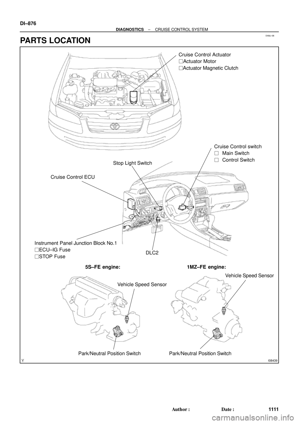
Stop Light SwitchCruise Control Actuator
� Actuator Motor
� Actuator Magnetic Clutch
Cruise Control ECUCruise Control switch
��Main Switch
��Control Switch
DLC2 Instrument Panel Junction Block No.1
� ECU±IG Fuse
� STOP Fuse
5S±FE engine: 1MZ±FE engine:
Vehicle Speed Sensor
Park/Neutral Position Switch Park/Neutral Position SwitchVehicle Speed Sensor
DI±876
± DIAGNOSTICSCRUISE CONTROL SYSTEM
1111 Author�: Date�:
PARTS LOCATION