Page 2946 of 4770
F03291
(±)
(+)12 A4
DI±526
± DIAGNOSTICSANTI±LOCK BRAKE SYSTEM (DENSO Made)
761 Author�: Date�:
INSPECTION PROCEDURE
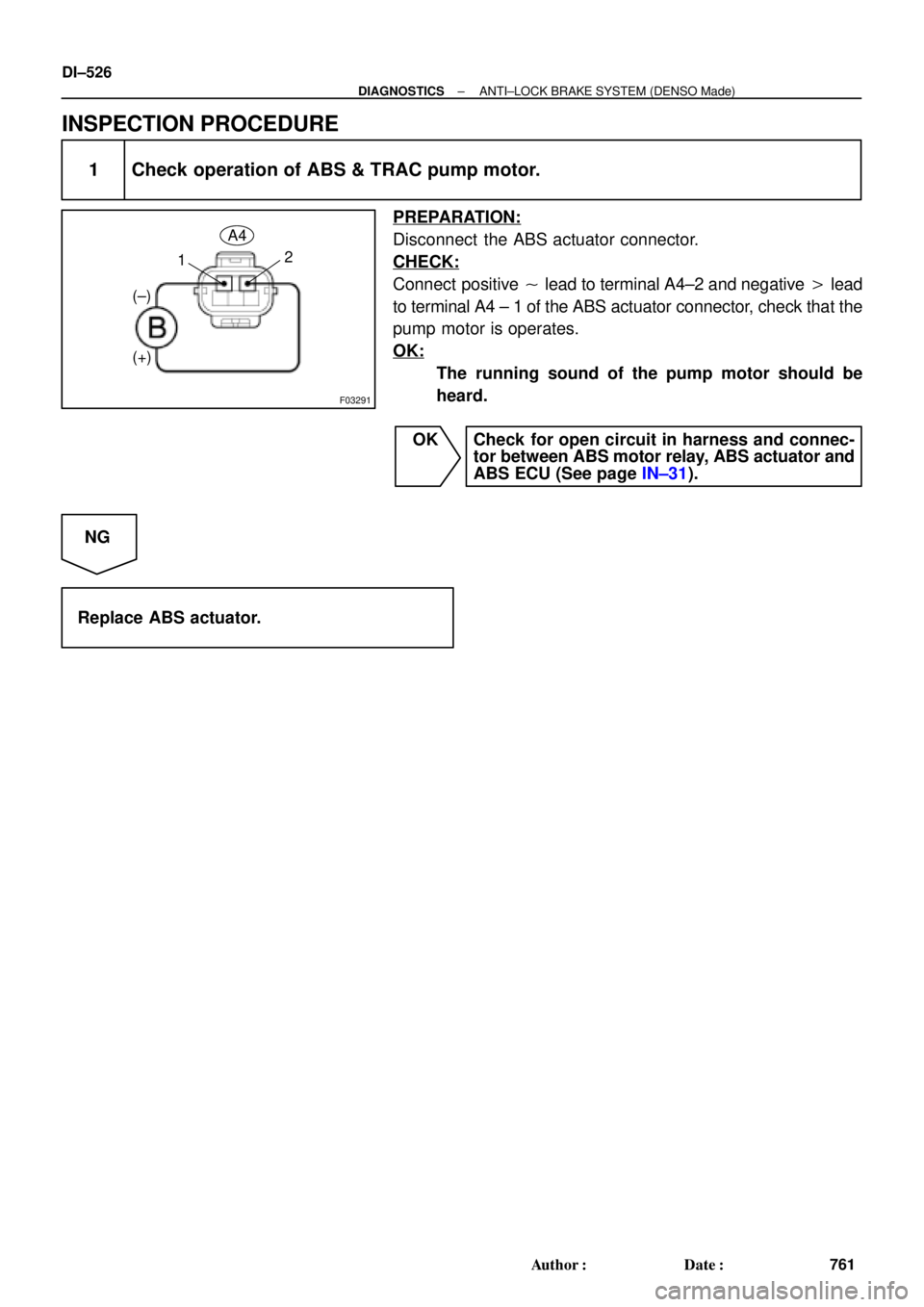
1 Check operation of ABS & TRAC pump motor.
PREPARATION:
Disconnect the ABS actuator connector.
CHECK:
Connect positive � lead to terminal A4±2 and negative � lead
to terminal A4 ± 1 of the ABS actuator connector, check that the
pump motor is operates.
OK:
The running sound of the pump motor should be
heard.
OK Check for open circuit in harness and connec-
tor between ABS motor relay, ABS actuator and
ABS ECU (See page IN±31).
NG
Replace ABS actuator.
Page 2949 of 4770

F07217
Engine Room R/B No. 3
ABS Solenoid Relay
3
ABS
Actuator
A4 1
2
5 BatteryGAUGE Instrument Panel J/B
J/C
J4
D
ABS ECU 33 3 3
EA34 6
ABS ECUD
IK28
R±L
II3 4
DLC1 R±L
G±B
II3 5 Short
Pin
W±B
ABS ECU W±L
G±B
C
CC R±L
R±L 1D2
7
4
R±L
A19WA IG3 12
11 G±B 4
G±B C10
C10
J/C
J29ABS Warning
Light
23
22 R±L
± DIAGNOSTICSANTI±LOCK BRAKE SYSTEM (DENSO Made)
DI±529
764 Author�: Date�:
ABS Warning Light Circuit
CIRCUIT DESCRIPTION
If the ECU detects trouble, it lights the ABS warning light while at the same time prohibiting ABS control. At
this time, the ECU records a DTC in memory.
After removing the short pin of the DLC1, connect terminals Tc and E
1 of the DLC1 or DLC2 to make the
ABS warning light blink and output the DTC.
WIRING DIAGRAM
INSPECTION PROCEDURE
Troubleshooting in accordance with the chart below for each trouble symptom.
ABS warning light does not light upGo to step 1
ABS warning light remains onGo to step 3
1 Check ABS warning light.
See combination meter troubleshooting on page BE±2.
NG Repair bulb or combination meter assembly.
OK
DI03Q±03
Page 2956 of 4770
F00071
DI±536
± DIAGNOSTICSANTI±LOCK BRAKE SYSTEM (DENSO Made)
771 Author�: Date�:
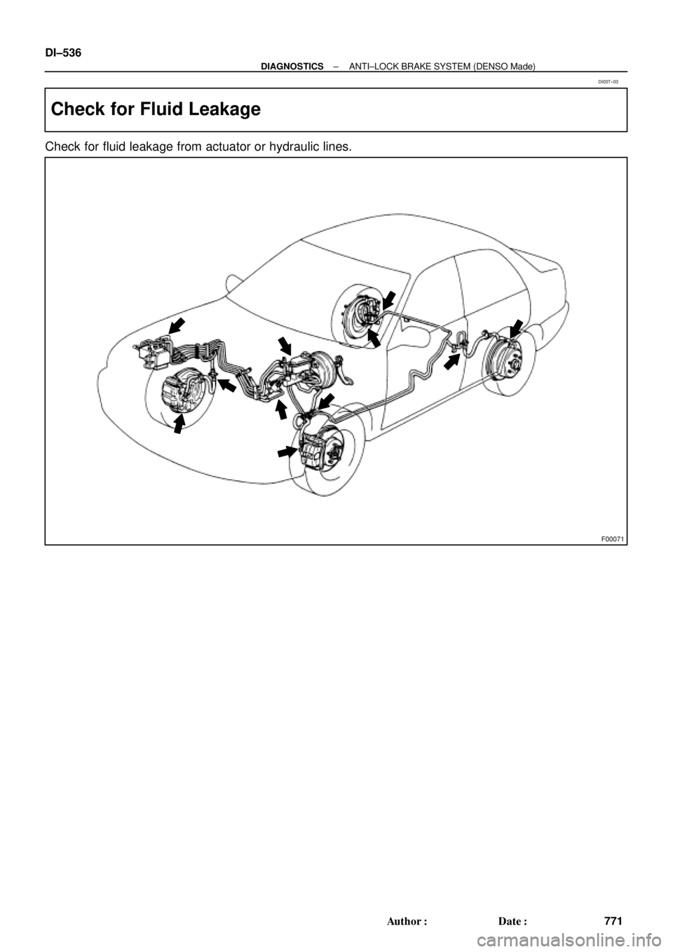
Check for Fluid Leakage
Check for fluid leakage from actuator or hydraulic lines.
DI03T±03
Page 2962 of 4770

777 Author�: Date�:
DIAGNOSTIC TROUBLE CODE CHART
HINT:
�Using SST 09843 ±18020, connect the terminals Tc and E1.
�If a malfunctio")
DI03W±11
DI±542
± DIAGNOSTICSANTI±LOCK BRAKE SYSTEM (BOSCH Made)
777 Author�: Date�:
DIAGNOSTIC TROUBLE CODE CHART
HINT:
�Using SST 09843 ±18020, connect the terminals Tc and E1.
�If a malfunction code is displayed during the DTC check, check the circuit listed for the code. For details
of each code, turn to the page referred to under the ºSee pageº for respective ºDTC No.º in the DTC
chart.
DTC No.
(See Page)Detection ItemTrouble Area
11
(DI±546)ABS solenoid valve relay faulty
�ABS solenoid valve relay
�Valve supply voltage
�ECU
13
(DI±548)ABS pump motor faulty
�ABS motor relay
�Pump motor voltage
�Pump motor lead disconnected
�ECU
21
(DI±550)Right front solenoid valves faulty�ABS actuator (right front inlet or outlet solenoid valve)
22
(DI±550)Left front solenoid valves faulty�ABS actuator (left front inlet or outlet solenoid valve)
23
(DI±550)Right rear solenoid valves faulty�ABS actuator (right rear inlet or outlet solenoid valve)
24
(DI±550)Left rear solenoid valves faulty�ABS actuator (left rear inlet or outlet solenoid valve)
31
(DI±552)Right front wheel speed sensor signal malfunction
32
(DI±552)Left front wheel speed sensor signal malfunction�Right front, left front, right rear and left rear speed sensor
�Each speed sensor circuit
33
(DI±552)Right rear wheel speed sensor signal malfunction
�Each s eed sensor circuit
�Sensor installation
�ECU
34
(DI±552)Left rear wheel speed sensor signal malfunction
35
(DI±552)Open circuit in right front wheel speed sensor circuit�Right front, left front speed sensor
Eh d i it36
(DI±552)Open circuit in left front wheel speed sensor circuit
�Each speed sensor circuit
�ECU
37
(DI±557)Speed sensor rotor is wrong number of teeth on one of the 4
wheels�Speed sensor
�Sensor rotor
�ECU
38
(DI±552)Open circuit in right rear wheel speed sensor circuit�Right rear, left rear speed sensor
Eh d i it39
(DI±552)Open circuit in left rear wheel speed sensor circuit
�Each speed sensor circuit
�ECU
41
(DI±558)Low battery positive voltage
�Battery
�Charging system regulator
�Power source circuit
�ECU
58
(DI±561)Open circuit in stop light switch circuit
�Stop light switch
�Stop light switch circuit
�ECU
62
(DI±563)Malfunction in ECU�ECU
Page 2963 of 4770
DI03X±05
F01175
ABS Actuator
(w/ ECU, Relay)Front Speed Sensor
DLC1
DLC2Sensor Rotor
Rear Speed Sensor
Stop Light Switch ABS Warning Light
Sensor Rotor
Front Speed Sensor
± DIAGNOSTICSANTI±LOCK BRAKE SYSTEM (BOSCH Made)
DI±543
778 Author�: Date�:
PARTS LOCATION
Page 2966 of 4770

DI040±08
F03949
Actuator Assembly
BatteryActuator Assembly
MAINB±GF4 1 ALT
FL
Block 1F5 B±G3
ABS
12 3
Engine
Room R/B
No.3L
L
18
A6
+B+BA6
Valve Relay
Motor Relay17
A6 16 GND2
W±BEA
W±B
W±B 19
A6GND1 ECU DI±546
± DIAGNOSTICSANTI±LOCK BRAKE SYSTEM (BOSCH Made)
781 Author�: Date�:
CIRCUIT INSPECTION
DTC 11 ABS Solenoid Valve Relay Circuit
CIRCUIT DESCRIPTION
This relay supplies power to each ABS solenoid. After the ignition switch is turned ON, if the initial check is
OK, the relay goes on.
DTC No.DTC Detecting ConditionTrouble Area
11
Detection of any conditions from 1. through 3.:
1. 3 or more solenoid valves are shown faulty in response
and simultaneously valve supply voltage is detected
faulty.
2. Solenoid valve relay will not be switched OFF.
3. Valve relay is frozen in spite of its high valve relay sup-
ply voltage.
�ABS solenoid valve relay
�Valve supply voltage
�ECU
Fail safe function:
If trouble occurs in the ABS solenoid valve relay circuit, the ECU cuts off current to the ABS solenoid valve
relay and prohibits ABS control.
WIRING DIAGRAM
Page 2967 of 4770
F00064
LOCK
191817
16
(+) (±) LOCK
191817
16
(+) (±)
A6 LOCK
191817
16
(+) (±)
± DIAGNOSTICSANTI±LOCK BRAKE SYSTEM (BOSCH Made)
DI±547
782 Author�: Date�:
INSPECTION PROCEDURE
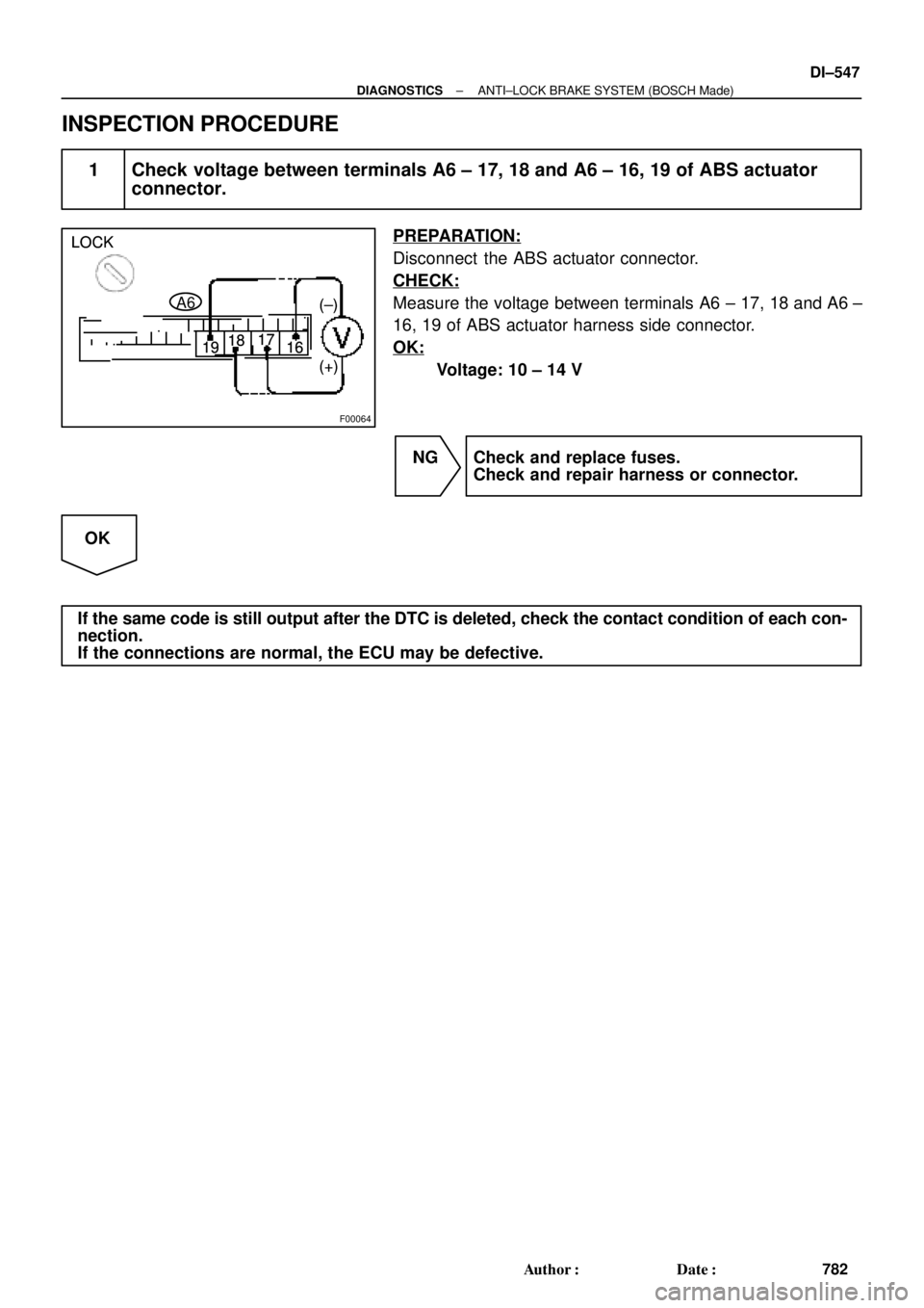
1 Check voltage between terminals A6 ± 17, 18 and A6 ± 16, 19 of ABS actuator
connector.
PREPARATION:
Disconnect the ABS actuator connector.
CHECK:
Measure the voltage between terminals A6 ± 17, 18 and A6 ±
16, 19 of ABS actuator harness side connector.
OK:
Voltage: 10 ± 14 V
NG Check and replace fuses.
Check and repair harness or connector.
OK
If the same code is still output after the DTC is deleted, check the contact condition of each con-
nection.
If the connections are normal, the ECU may be defective.
Page 2968 of 4770

F03949
Actuator Assembly
BatteryActuator Assembly
MAINB±GF4 1 ALT
FL
Block 1F5 B±G3
ABS
12 3L
L
18
A6
+B+BA6
Valve Relay
Motor Relay17
A6 16 GND2
W±BEA
W±B
W±B 19
A6GND1 ECU Engine
Room R/B
No.3 DI±548
± DIAGNOSTICSANTI±LOCK BRAKE SYSTEM (BOSCH Made)
783 Author�: Date�:
DTC 13 Pump Motor Circuit
CIRCUIT DESCRIPTION
The ABS motor relay supplies power to the ABS pump motor. While the ABS is activated, the ECU switches
the ABS motor relay ON and operates the ABS pump motor.
DTC No.DTC Detecting ConditionTrouble Area
13
Detection of any conditions from (1) through (3):
1. After actuation of the motor relay, pump motor voltage
will not be supplied within 0.4 sec.
2. Pump motor voltage is at a high level, motor relay will
not actuate for 2.5 sec. or more.
3. Pump motor voltage keeps low level for longer than 0.4
sec. and the pump repeats activating for 7 sec. 3 times
maximally. since the last activation, the pump motor has
been gone dead because of short circuit.
�ABS motor relay
�Pump motor voltage
�Pump motor lead disconnected
�ECU
Fail safe function:
If trouble occurs in the ABS motor relay circuit, the ECU cuts off current to the ABS solenoid relay and prohib-
its ABS control.
WIRING DIAGRAM
DI041±08
Front Speed Sensor
DLC1
DLC2Sensor Rotor
Rear Speed Sensor
Stop Light Switch ABS Warning Light
Sensor Rotor
Front Speed Sensor
± DIAGNOSTICSANTI±LOCK BRA")