Page 2287 of 4770
BR078±03
W03245
SST
± BRAKEABS & TRAC ACTUATOR
BR±65
2088 Author�: Date�:
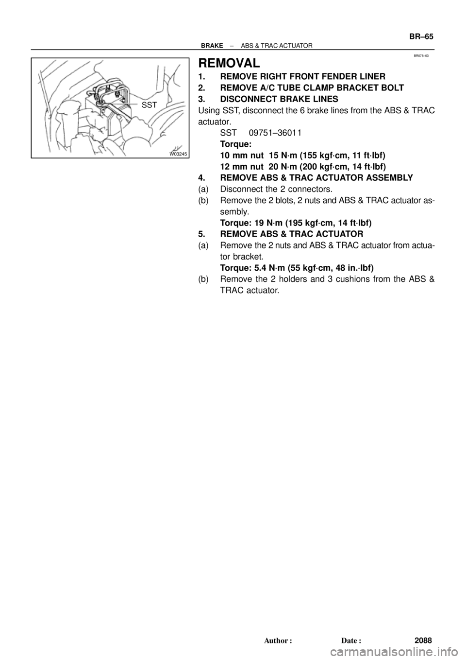
REMOVAL
1. REMOVE RIGHT FRONT FENDER LINER
2. REMOVE A/C TUBE CLAMP BRACKET BOLT
3. DISCONNECT BRAKE LINES
Using SST, disconnect the 6 brake lines from the ABS & TRAC
actuator.
SST 09751±36011
Torque:
10 mm nut 15 N´m (155 kgf´cm, 11 ft´lbf)
12 mm nut 20 N´m (200 kgf´cm, 14 ft´lbf)
4. REMOVE ABS & TRAC ACTUATOR ASSEMBLY
(a) Disconnect the 2 connectors.
(b) Remove the 2 blots, 2 nuts and ABS & TRAC actuator as-
sembly.
Torque: 19 N´m (195 kgf´cm, 14 ft´lbf)
5. REMOVE ABS & TRAC ACTUATOR
(a) Remove the 2 nuts and ABS & TRAC actuator from actua-
tor bracket.
Torque: 5.4 N´m (55 kgf´cm, 48 in.´lbf)
(b) Remove the 2 holders and 3 cushions from the ABS &
TRAC actuator.
Page 2288 of 4770
BR079±03
BR±66
± BRAKEABS & TRAC ACTUATOR
2089 Author�: Date�:
INSTALLATION
Installation is in the reverse order of removal (See page BR±65).
HINT:
�After installation, fill the brake reservoir with brake fluid and bleed the brake system.
(See page BR±4)
�Check for leaks.
Page 2340 of 4770
CL03G±01
Q10092
Starter
21 (210, 15)
39 (400, 29)
13 (130, 9)13 (130, 9)
Clutch Accumulator Bracket
N´m (kgf´cm, ft´lbf)
: Specified torqueCruise Control
Actuator
Battery w/ Cruise Control System :
27 (270, 20)
15 (155, 11)
CL±14
± CLUTCHCLUTCH ACCUMULATOR (1MZ±FE)
1793 Author�: Date�:
CLUTCH ACCUMULATOR (1MZ±FE)
COMPONENTS
Page 2341 of 4770
CL03H±01
Q10074
Q10078
Q10076
SST
± CLUTCHCLUTCH ACCUMULATOR (1MZ±FE)
CL±15
1794 Author�: Date�:
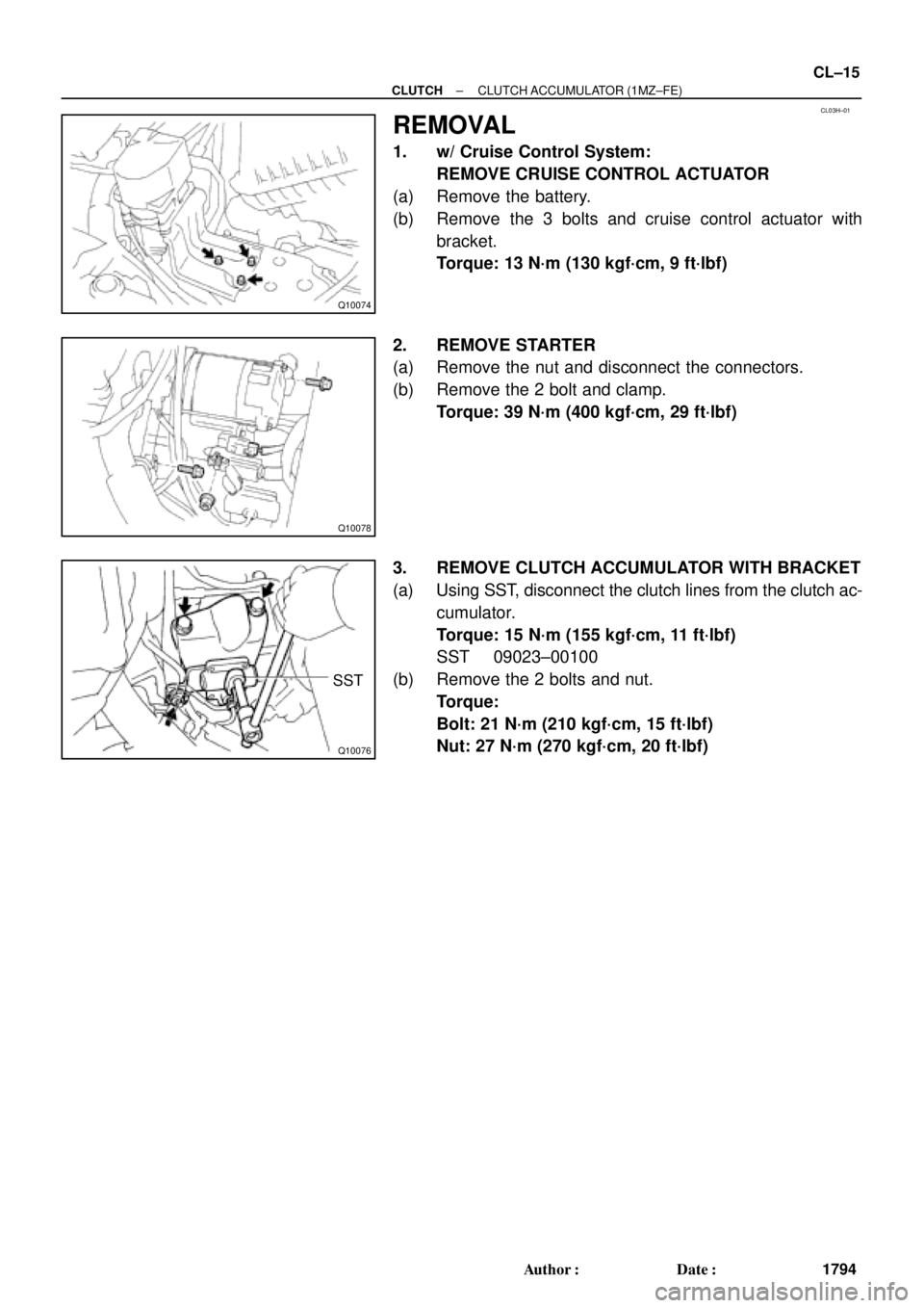
REMOVAL
1. w/ Cruise Control System:
REMOVE CRUISE CONTROL ACTUATOR
(a) Remove the battery.
(b) Remove the 3 bolts and cruise control actuator with
bracket.
Torque: 13 N´m (130 kgf´cm, 9 ft´lbf)
2. REMOVE STARTER
(a) Remove the nut and disconnect the connectors.
(b) Remove the 2 bolt and clamp.
Torque: 39 N´m (400 kgf´cm, 29 ft´lbf)
3. REMOVE CLUTCH ACCUMULATOR WITH BRACKET
(a) Using SST, disconnect the clutch lines from the clutch ac-
cumulator.
Torque: 15 N´m (155 kgf´cm, 11 ft´lbf)
SST 09023±00100
(b) Remove the 2 bolts and nut.
Torque:
Bolt: 21 N´m (210 kgf´cm, 15 ft´lbf)
Nut: 27 N´m (270 kgf´cm, 20 ft´lbf)
Page 2917 of 4770

DI±497
732 Author�: Date�:
DIAGNOSTIC TROUBLE CODE CHART
HINT:
�Using SST 09843 ±18020, connect the terminals Tc and E1, and remove the s")
DI03D±03
± DIAGNOSTICSANTI±LOCK BRAKE SYSTEM (DENSO Made)
DI±497
732 Author�: Date�:
DIAGNOSTIC TROUBLE CODE CHART
HINT:
�Using SST 09843 ±18020, connect the terminals Tc and E1, and remove the short pin.
�If any abnormality is not found when inspection parts, inspect the ECU.
�If a malfunction code is displayed during the DTC check, check the circuit listed for the code. For details
of each code, turn to the page referred to under the ºSee pageº for respective ºDTC No.º in the DTC
chart.
DTC No.
(See Page)Detection ItemTrouble Area
11
(DI±502)Open circuit in ABS solenoid relay circuit�ABS solenoid relay
12
(DI±502)Short circuit in ABS solenoid relay circuit
�ABS solenoid relay
�ABS solenoid relay circuit
13
(DI±507)Open circuit in ABS motor relay circuit�ABS motor relay
14
(DI±507)Short circuit in ABS motor relay circuit
�ABS motor relay
�ABS motor relay circuit
21
(DI±511)Open or short circuit in 2±position solenoid circuit for right front
wheel�ABS actuator
�SFRR or SFRH circuit
22
(DI±511)Open or short circuit in 2±position solenoid circuit for left front
wheel�ABS actuator
�SFLR or SFLH circuit
23
(DI±511)Open or short circuit in 2±position solenoid circuit for right rear
wheel�ABS actuator
�SRRR or SRRH circuit
24
(DI±511)Open or short circuit in 2±position solenoid circuit for left rear
wheel�ABS actuator
�SRLR or SRLH circuit
31
(DI±514)Right front wheel speed sensor signal malfunction
32
(DI±514)Left front wheel speed sensor signal malfunction�Right front, left front, right rear and left rear speed sensor
Eh d i it33
(DI±514)Right rear wheel speed sensor signal malfunction
�Each speed sensor circuit
�Speed sensor rotor
34
(DI±514)Left rear wheel speed sensor signal malfunction
33, 34
(DI±519)Rear speed sensor rotor faulty
�Rear axle hub
�Right rear, left rear speed sensor
�Rear speed sensor circuit
41
(DI±520)Power source voltage down
�Battery
�Charging system
�Power source circuit
49
(DI±523)Open circuit in stop light switch circuit�Stop light switch
�Stop light switch circuit
51
(DI±525)Pump motor is locked�ABS pump motor
Always ON
(DI±527)Malfunction in ECU�ECU
�Battery
Page 2918 of 4770
DI03E±03
F01172
Sensor Rotor
ABS Warning Light
ABS ECU
DLC 1
Front Speed Sensor
ABS Actuator
ABS Solenoid
Relay
ABS Motor Relay
Sensor RotorFront Speed
Sensor
Stop Light SwitchDLC 2
Rear Speed Sensor DI±498
± DIAGNOSTICSANTI±LOCK BRAKE SYSTEM (DENSO Made)
733 Author�: Date�:
PARTS LOCATION
Page 2921 of 4770

DI±501
736 Author�: Date�:
PROBLEM SYMPTOMS TABLE
If a normal code is displayed during the DTC check but the problem still occurs, check t")
DI03G±04
± DIAGNOSTICSANTI±LOCK BRAKE SYSTEM (DENSO Made)
DI±501
736 Author�: Date�:
PROBLEM SYMPTOMS TABLE
If a normal code is displayed during the DTC check but the problem still occurs, check the circuits for each
problem symptom in the order given in the table below and proceed to the relevant troubleshooting page.
SymptomSuspect AreaSee page
ABS does not operate
Only when 1. to 4. are all normal and the problem is still
occurring, replace the ABS ECU.
13.Check the DTC reconfirming that the normal code is
output.
14.IG power source circuit.
15.Speed sensor circuit.
16.Check the ABS actuator with a checker.
If abnormal, check the hydraulic circuit for leakage
(See page DI±536).
DI±493
DI±520
DI±514
BR±50
ABS does not operate efficiently
Only when 1. to 4. are all normal and the problem is still
occurring, replace the ABS ECU.
1. Check the DTC reconfirming that the normal code is
output.
2. Speed sensor circuit
3. Stop light switch circuit
4. Check the ABS actuator with a checker.
If abnormal, check the hydraulic circuit for leakage
(See page DI±536).
DI±493
DI±514
DI±523
BR±50
ABS warning light abnormal1. ABS warning light circuit
2. ABS ECUDI±529
DI±527
DTC check cannot be done
Only when 1. and 2. are all normal and the problem is still
occurring, replace the ABS ECU.
1. ABS warning light circuit
2. Tc terminal circuit
DI±529
DI±532
Speed sensor signal check cannot be done1. Ts terminal circuit
2. ABS ECUDI±534
DI±527
Page 2923 of 4770
F07147
ABS Solenoid RelayGR±R1
IK1
GR±RABS ECU
26
A19R+
34
56
33
3
3 1
2 DLC1Engine Room
R/B No.3
GR
7
2ABS
1
3
W±L
B±G
Fusible Link Block
1
F5 F41
B±G
FL Main
Battery ALT
EAW±B4
A4A18 SR
ABS
Actuator
1
A5
A55
A53
7
A5
A5
A5
A5
A54
8
2
6R±B
W±R11
IK2
IK212R±B
W±R2
A19
A191
A18
A18
A18
A18
A19
A19 L±B
W±L
W±R
R±G
G±Y
LG±B13
IK2
IK255
6
11
12
15
14SFRH
SFRR
SFLH
SFLR
SRRH
SRRR
SRLH
SRLR 3
G±Y
LG±B
± DIAGNOSTICSANTI±LOCK BRAKE SYSTEM (DENSO Made)
DI±503
738 Author�: Date�:
WIRING DIAGRAM


39 (400, 29)
13 (130, 9)13 (130, 9)
Clutch Accumulator Bracket
N´m (kgf´cm, ft´lbf)
: Specified torqueCruise Control
Actuator
Battery w/ Cruise Control System")