Page 1951 of 4770
AUTOMATIC TRANSAXLE UNIT
AX±23
1943 Author�: Date�:
REMOVAL
1. REMOVE BATTERY
2. REMOVE AIR CLEANER ASSEMBLY
3. REMOVE THROT")
AX03Y±01
Q00225
Q09982
Q10287
Q00075
Q10028
± AUTOMATIC TRANSAXLE (A541E)AUTOMATIC TRANSAXLE UNIT
AX±23
1943 Author�: Date�:
REMOVAL
1. REMOVE BATTERY
2. REMOVE AIR CLEANER ASSEMBLY
3. REMOVE THROTTLE CABLE FROM THROTTLE
BODY
Torque: 15 N´m (150 kgf´cm, 11 ft´lbf)
4. w/ Cruise Control:
REMOVE CRUISE CONTROL ACTUATOR
(a) Disconnect the connector.
(b) Remove the 3 bolts and disconnect cruise control actua-
tor with the bracket.
Torque: 13 N´m (130 kgf´cm, 9 ft´lbf)
5. DISCONNECT GROUND CABLE
6. DISCONNECT VEHICLE SPEED SENSOR CONNEC-
TOR
7. DISCONNECT DIRECT CLUTCH SPEED SENSOR
CONNECTOR
8. DISCONNECT PARK/NEUTRAL POSITION SWITCH
CONNECTOR
9. DISCONNECT SOLENOID CONNECTOR
10. DISCONNECT SHIFT CONTROL CABLE
(a) Remove the nut and disconnect the shift control cable
from the park/neutral position switch.
Torque: 15 N´m (150 kgf´cm, 11 ft´lbf)
(b) Remove the clip and disconnect the shift control cable.
11. REMOVE 2 ENGINE MOUNTING ABSORBER BOLTS
Torque: 48 N´m (490 kgf´cm, 35 ft´lbf)
Page 2272 of 4770
 Sub±Wire Harness G (SST)
ABSSub±Wire Harness L (SST)
Sub±Wire Harness I (SST) ActuatorABS Actuator Checker BR±50
± BRAKEABS ACTUATOR (DENSO Made)
2073 Author�: Date�")
BR0BD±02
W03244
R09422
(SST) Sub±Wire Harness G (SST)
ABSSub±Wire Harness L (SST)
Sub±Wire Harness I (SST) ActuatorABS Actuator Checker BR±50
± BRAKEABS ACTUATOR (DENSO Made)
2073 Author�: Date�:
ABS ACTUATOR (DENSO Made)
ON±VEHICLE INSPECTION
HINT:
Using the ABS actuator checker (SST), check the operation of
the actuator. If the actuator does not operate, check the opera-
tion of sub±wire harness G according to the instructions on
pages DI±502 and DI±507. If the solenoid and/or pump motor
relay are abnormal, replace the relay and inspect the actuator
operation again.
1. INSPECT BATTERY POSITIVE VOLTAGE
Battery positive voltage: 10 ± 14 V
2. DISCONNECT CONNECTORS
Disconnect the 2 connectors from the actuator.
3. CONNECT ACTUATOR CHECKER (SST)
(a) Connect the actuator checker (SST) to the actuator side
wire harness via the sub±wire harness (SST), as shown.
SST 09990±00150, 09990±00250, 09990±00300,
09990±00360
(b) Connect the red cable of the checker to the battery posi-
tive (+) terminal and black cable to the negative (±) termi-
nal. Connect the black cable of the sub±wire harness to
the battery negative (±) terminal or body ground.
Page 2273 of 4770

BR±51
2074 Author�: Date�:
(c) Place the ºSHEET Pº (SST) on the actuator checker.
SST SST 09990±00430
4. INSPECT BRAKE ACTUATOR")
F07214
W03269
W03270
W03268
W03271
± BRAKEABS ACTUATOR (DENSO Made)
BR±51
2074 Author�: Date�:
(c) Place the ºSHEET Pº (SST) on the actuator checker.
SST SST 09990±00430
4. INSPECT BRAKE ACTUATOR OPERATION
(a) Start the engine, and run it at idle.
(b) Turn the selector switch of the actuator checker to
ºFRONT LHº position.
(c) Push and hold in the MOTOR switch for a few seconds.
(d) Depress the brake pedal and hold it until step (g) is com-
pleted.
(e) Push the MAIN push switch, and check that the brake
pedal does not go down.
NOTICE:
Do not keep the MAIN push switch pushed down for more
than 10 seconds.
(f) Release the switch, and check that the pedal goes down.
(g) Push and hold in the MOTOR switch for a few seconds,
and check that the pedal returns.
(h) Release the brake pedal.
(i) Push and hold in the MOTOR switch for a few seconds.
(j) Depress the brake pedal and hold it for about 15 seconds.
As you hold the pedal down, push the MOTOR switch for
a few seconds. Check that the brake pedal does not pul-
sate.
(k) Release the brake pedal.
(l) Turn the selector switch to ºREAR RHº position.
(m) Repeat (c) to (j), checking the actuator operation similarly.
(n) Similarly, inspect ºREAR LHº and ºFRONT RHº position.
HINT:
When inspecting ºFRONT RHº position, push the FRONT RH
switch instead of the MAIN push switch, and you can inspect in
any selector switch position.
Page 2274 of 4770
W03267
BR±52
± BRAKEABS ACTUATOR (DENSO Made)
2075 Author�: Date�:
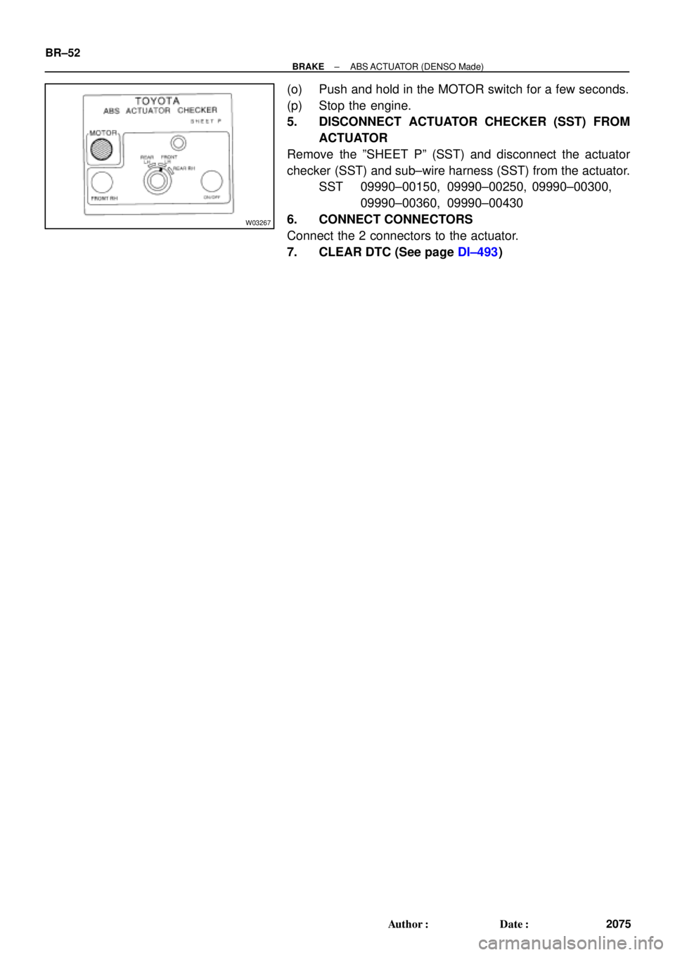
(o) Push and hold in the MOTOR switch for a few seconds.
(p) Stop the engine.
5. DISCONNECT ACTUATOR CHECKER (SST) FROM
ACTUATOR
Remove the ºSHEET Pº (SST) and disconnect the actuator
checker (SST) and sub±wire harness (SST) from the actuator.
SST 09990±00150, 09990±00250, 09990±00300,
09990±00360, 09990±00430
6. CONNECT CONNECTORS
Connect the 2 connectors to the actuator.
7. CLEAR DTC (See page DI±493)
Page 2275 of 4770
BR0BE±02
W03266
ABS Actuator
Cushion
Holder
Cushion
Actuator BracketA/C Tube Clamp
Bracket
N´m (kgf´cm, ft´lbf) : Specified torque
15 (155, 11)5.4 (55, 48 in.´lbf)
19 (195, 14)
19 (195, 14)
± BRAKEABS ACTUATOR (DENSO Made)
BR±53
2076 Author�: Date�:
COMPONENTS
Page 2276 of 4770
BR0BF±02
W03243
SST BR±54
± BRAKEABS ACTUATOR (DENSO Made)
2077 Author�: Date�:
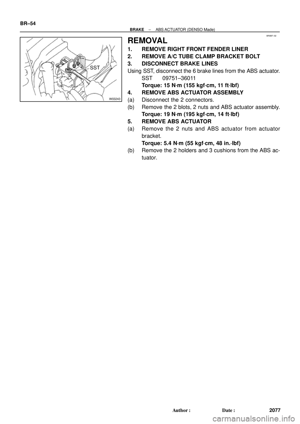
REMOVAL
1. REMOVE RIGHT FRONT FENDER LINER
2. REMOVE A/C TUBE CLAMP BRACKET BOLT
3. DISCONNECT BRAKE LINES
Using SST, disconnect the 6 brake lines from the ABS actuator.
SST 09751±36011
Torque: 15 N´m (155 kgf´cm, 11 ft´lbf)
4. REMOVE ABS ACTUATOR ASSEMBLY
(a) Disconnect the 2 connectors.
(b) Remove the 2 blots, 2 nuts and ABS actuator assembly.
Torque: 19 N´m (195 kgf´cm, 14 ft´lbf)
5. REMOVE ABS ACTUATOR
(a) Remove the 2 nuts and ABS actuator from actuator
bracket.
Torque: 5.4 N´m (55 kgf´cm, 48 in.´lbf)
(b) Remove the 2 holders and 3 cushions from the ABS ac-
tuator.
Page 2277 of 4770
BR0BG±02
± BRAKEABS ACTUATOR (DENSO Made)
BR±55
2078 Author�: Date�:
INSTALLATION
Installation is in the reverse order of removal (See page BR±54).
HINT:
�After installation, fill the brake reservoir with brake fluid, bleed the brake system (See page BR±4).
�Check for leaks.
Page 2278 of 4770
BR0BH±03
W03327
Holder
Cushion
CushionA/C Tube Clamp Bracket ABS Actuator
(w/ ECU)
Actuator Bracket
N´m (kgf´cm, ft´lbf): Specified torque
9.0 (92, 80 in.´lbf)
15 (155, 11)
19 (195, 14)
19 (195, 14)
F07215
Actuator ECU
� Non±reusable part
N´m (kgf´cm, ft´lbf): Specified torque�
2.6 (27, 23 in.´lbf)
BR±56
± BRAKEABS ACTUATOR (BOSCH Made)
2079 Author�: Date�:
ABS ACTUATOR (BOSCH Made)
COMPONENTS
 : Specified torque
15 (155, 11)5.4 (55, 48 in.´lbf)
19 (195, 14)
19 (195, 14)
± BR")


Actuator Bracket
N´m (kgf´cm, ft´lbf): Specified torque
9.0 (92, 80 in.´lbf)
15 (155, 11)
19 (195, 14)
19 (195,")