Page 4025 of 4770

SS09Y±03
± SERVICE SPECIFICATIONSBRAKE
SS±63
226 Author�: Date�:
TORQUE SPECIFICATION
Part tightenedN´mkgf´cmft´lbf
Master cylinder x Piston stopper bolt101007
Master cylinder x Reservoir1.71816 in.´lbf
Master cylinder x Brake booster131309
Brake line union nut 10 mm nut1515511
12 mm nut2020014
Brake booster clevis lock nut2526019
Brake booster x Pedal bracket131309
Brake pedal x Pedal bracket3940029
Pedal bracket x Instrument panel reinforcement131309
Front brake caliper installation bolt3435025
Bleeder plug8.38574 in.´lbf
Front brake torque plate x Steering knuckle1071,09079
Front brake caliper x Flexible hose2930021
Flexible hose x Shock absorber bracket2930021
Rear drum brake wheel cylinder x Backing plate101007
Parking brake cable bracket x Backing plate7.88069 in.´lbf
Rear brake caliper installation bolt2020014
Rear disc brake cariper main pin installation bolt2627020
Rear brake caliper x Flexible hose2930021
Rear brake torque plate x Rear axle carrier4747534
Proportioning valve installation bolt8.89078 in.´lbf
ABS actuator x Actuator bracket DENSO type5.45548 in.´lbf
ABS actuator x Actuator bracket BOSCH type9.09280 in.´lbf
ABS actuator x ECU BOSCH type2.62723 in.´lbf
ABS & TRAC actuator x Actuator bracket5.45548 in.´lbf
ABS (& TRAC) actuator bracket x Body1919514
Front speed sensor installation bolt7.88069 in.´lbf
Front speed sensor harness clamp bolt5.45548 in.´lbf
Rear speed sensor installation bolt7.88069 in.´lbf
Rear speed sensor harness clamp bolt5.45548 in.´lbf
Page 4028 of 4770
SS061±17
SS±66
± SERVICE SPECIFICATIONSSUPPLEMENTAL RESTRAINT SYSTEM
229 Author�: Date�:
SUPPLEMENTAL RESTRAINT SYSTEM
TORQUE SPECIFICATION
Part tightenedN´mkgf´cmft´lbf
Steering wheel3536026
Steering wheel pad7.17263 in.´lbf
Front passenger airbag assembly x Instrument panel reinforcement2020515
Front seat installation bolt3737527
Seatback frame set bolt Bolt A
(See page RS±49) Bolt B18
15185
15013
11
Airbag sensor assembly2020515
Front airbag sensor2020515
Side airbag sensor assembly2020515
Front seat outer belt retractor Upper bolt
Lower bolt7.5
4276
43066 in.´lbf
31
Page 4035 of 4770
SFI SYSTEM
SF±1
1434 Author�: Date�:
SFI SYSTEM
PRECAUTION
1. BEFORE WORKING ON FUEL SYSTEM, DISCON-
NECT NEGATIVE (±) TERMINAL CABLE FROM BAT-
TERY
HINT:
Any diagnostic tro")
SF0D6±04
± SFI (5S±FE)SFI SYSTEM
SF±1
1434 Author�: Date�:
SFI SYSTEM
PRECAUTION
1. BEFORE WORKING ON FUEL SYSTEM, DISCON-
NECT NEGATIVE (±) TERMINAL CABLE FROM BAT-
TERY
HINT:
Any diagnostic trouble code retained by the computer will be
erased when the negative (±) terminal cable is removed from
the battery.
Therefore, if necessary, read the diagnosis before removing the
negative (±) terminal cable from the battery.
2. DO NOT SMOKE OR WORK NEAR AN OPEN FLAME
WHEN WORKING ON THE FUEL SYSTEM
3. KEEP GASOLINE AWAY FROM RUBBER OR LEATH-
ER PARTS
4. MAINTENANCE PRECAUTIONS
(a) In event of engine misfire, these precautions should be
taken.
(1) Check proper connection to battery terminals, etc.
(2) After repair work, check that the ignition coil termi-
nals and all other ignition system lines are recon-
nected securely.
(3) When cleaning the engine compartment, be espe-
cially careful to protect the electrical system from
water.
(b) Precautions when handling the oxygen sensor.
(1) Do not allow oxygen sensor to drop or hit against an
object.
(2) Do not allow the sensor to come into contact with
water.
5. IF VEHICLE IS EQUIPPED WITH MOBILE RADIO SYS-
TEM (HAM, CB, ETC.)
If the vehicle is equipped with a mobile communication system,
refer to the precaution in the IN section.
6. AIR INDUCTION SYSTEM
(a) Separation of the engine oil dipstick, oil filler cap, PCV
hose, etc. may cause the engine to run out of tune.
(b) Disconnection, looseness or cracks in the parts of the air
induction system between the throttle body and cylinder
head will allow air suction and cause the engine to run out
of tune.
7. ELECTRONIC CONTROL SYSTEM
(a) Before removing SFI wiring connectors, terminals, etc.,
first disconnect the power by either turning the ignition
switch OFF or disconnecting the negative (±) terminal
cable from the battery.
HINT:
Always check the diagnostic trouble code before disconnecting
the negative (±) terminal cable from the battery.
Page 4061 of 4770

Before installing the heated oxygen sensor,
twist the sensor wire counterclockwise
3 and 1/2 turns. HINT:
After installing the heated oxygen sen")
SF0DL±03
B06469
Heated Oxygen Sensor (Bank 1 Sensor 2)
Before installing the heated oxygen sensor,
twist the sensor wire counterclockwise
3 and 1/2 turns. HINT:
After installing the heated oxygen sensor,
check that the sensor wire is not twisted,
if it is twisted, remove the heated oxygen
sensor and reinstall it. �Location of Fuel Tank Cushion
No.1 Fuel Tank
Protector
Fuel Tank Vent
Tube Set Plate
Fuel Pump
Fuel Outlet Tube
Fuel Inlet Pipe Fuel Inlet Pipe Shield
Fuel Tank Cap
Fuel Inlet Pipe Protector
Heated Oxygen Sensor
(Bank 1 Sensor 2)Heat Insulator
Fuel Tank Band
Center Exhaust Pipe � Gasket� Gasket � Gasket
� Non±reusable part
N´m (kgf´cm, ft´lbf): Specified torque
39 (400, 29)
44 (450, 33)
56 (570, 41)
56 (570, 41)
x 8
�
� Gasket
Fuel TankFuel Inlet Hose
Charcoal
Canister
EVAP Line Hose Vent Line Hose
± SFI (5S±FE)FUEL TANK AND LINE
SF±27
1460 Author�: Date�:
FUEL TANK AND LINE
COMPONENTS
CAUTION:
�Always use new gaskets when replacing the fuel tank or component parts.
�Apply the proper torque to all parts tightened
Page 4063 of 4770
THROTTLE BODY
SF±29
1462 Author�: Date�:
THROTTLE BODY
ON±VEHICLE INSPECTION
1. INSPECT THROTTLE B")
B01277
Move
SF0DN±03
B00525
P
R
E
B01278
Disconnect
Vacuum
B01282
VTA
E2
VCOhmmeter
± SFI (5S±FE)THROTTLE BODY
SF±29
1462 Author�: Date�:
THROTTLE BODY
ON±VEHICLE INSPECTION
1. INSPECT THROTTLE BODY
(a) Check that the throttle linkage moves smoothly.
(b) Check the vacuum at each port.
�Start the engine.
�Check the vacuum with your finger.
Port nameAt idleOther than idle
Mark EVacuumVacuum
Mark PNo vacuumVacuum
Mark RNo vacuumNo vacuum
2. INSPECT THROTTLE POSITION SENSOR
(a) Disconnect the sensor connector.
(b) Disconnect the vacuum hose from the throttle opener.
(c) Apply vacuum to the throttle opener.
(d) Using an ohmmeter, measure the resistance between
each terminal.
Clearance between
lever and stop screwBetween
terminalsResistance
0 mm (0 in.)VTA ± E20.2 ± 5.7 kW
Throttle valve fully
openVTA ± E22.0 ± 10.2 kW
±VC ± E22.5 ± 5.9 kW
(e) Reconnect the vacuum hose to the throttle opener.
(f) Reconnect the sensor connector.
3. INSPECT THROTTLE OPENER
(a) Allow the engine to warm up to normal operating tempera-
ture.
Page 4065 of 4770
SF0DO±03
B00526
Accelerator Cable
Throttle Cable
(A/T)
Throttle Position Sensor
Connector
IAC Valve Connector
Water Bypass Hose
EVAP Hose
IAT Sensor
Connector
VSV Connector
for EVAP Air Cleaner CapPCV Hose Air Cleaner HoseThrottle Body Vacuum Hose
� Gasket
EVAP Hose
EVAP Hose Air Hose
(California)
N´m (kgf´cm, ft´lbf): Specified torque
� Non±reusable part
19 (195, 14)
± SFI (5S±FE)THROTTLE BODY
SF±31
1464 Author�: Date�:
COMPONENTS
Page 4066 of 4770
SF0DP±03
B01283
S05534
Water
Bypass
Hose
Water
Bypass
HoseAir
Hose SF±32
± SFI (5S±FE)THROTTLE BODY
1465 Author�: Date�:
REMOVAL
1. DRAIN ENGINE COOLANT
2. REMOVE AIR CLEANER CAP (See page EM±69)
3. DISCONNECT ACCELERATOR CABLE FROM
THROTTLE BODY
4. A/T:
DISCONNECT THROTTLE CABLE FROM THROTTLE
BODY
5. REMOVE THROTTLE BODY
(a) Disconnect the throttle position sensor connector.
(b) Disconnect the IAC valve connector.
(c) Disconnect the 2 vacuum hoses from the throttle body.
(d) Remove the 3 bolts.
(e) Disconnect the throttle body from the intake manifold.
(f) Remove the gasket.
(g) Disconnect the air hose for air assist system (California)
and the 2 water bypass hoses from the throttle body, and
remove the throttle body.
Page 4067 of 4770
SF0DQ±03
B00527
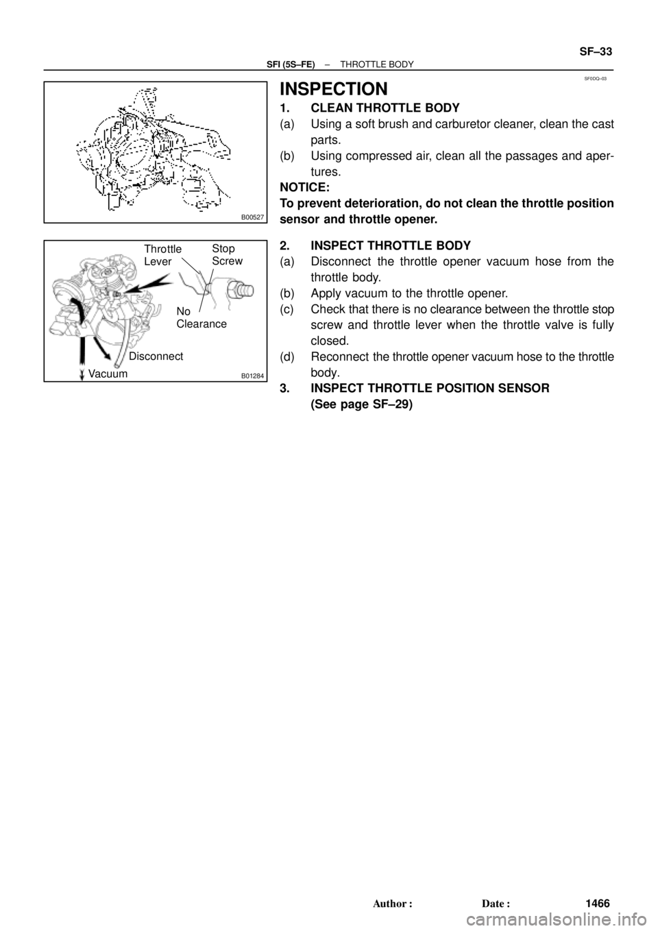
B01284
No
Clearance
Disconnect
VacuumThrottle
LeverStop
Screw
± SFI (5S±FE)THROTTLE BODY
SF±33
1466 Author�: Date�:
INSPECTION
1. CLEAN THROTTLE BODY
(a) Using a soft brush and carburetor cleaner, clean the cast
parts.
(b) Using compressed air, clean all the passages and aper-
tures.
NOTICE:
To prevent deterioration, do not clean the throttle position
sensor and throttle opener.
2. INSPECT THROTTLE BODY
(a) Disconnect the throttle opener vacuum hose from the
throttle body.
(b) Apply vacuum to the throttle opener.
(c) Check that there is no clearance between the throttle stop
screw and throttle lever when the throttle valve is fully
closed.
(d) Reconnect the throttle opener vacuum hose to the throttle
body.
3. INSPECT THROTTLE POSITION SENSOR
(See page SF±29)


Throttle Position Sensor
Connector
IAC Valve Connector
Water Bypass Hose
EVAP Hose
IAT Sensor
Connector
VSV Connector
for EVAP Air Cleaner CapPC")