Page 3770 of 4770
MANUAL TRANSAXLE ASSEMBLY
MX±11
1861 Author�: Date�:
DISASSEMBLY
1. REMOVE RELEASE FORK AND BEARING
2. REMOVE BACK±UP LIGHT SWITCH
Torque: 44 N´m (450")
MX04G±02
Z18142FIPG
± MANUAL TRANSAXLE (S51)MANUAL TRANSAXLE ASSEMBLY
MX±11
1861 Author�: Date�:
DISASSEMBLY
1. REMOVE RELEASE FORK AND BEARING
2. REMOVE BACK±UP LIGHT SWITCH
Torque: 44 N´m (450 kgf´cm, 33 ft´lbf)
3. REMOVE BOLT AND VEHICLE SPEED SENSOR
Torque: 5.4 N´m (55 kgf´cm, 48 in.´lbf)
4. REMOVE RELEASE BEARING RETAINER
Remove the 3 bolts and retainer.
Torque: 7.4 N´m (75 kgf´cm, 65 in.´lbf)
5. REMOVE SELECTING BELLCRANK
Remove the 2 bolts and selecting bellcrank.
Torque: 37 N´m (380 kgf´cm, 27 ft´lbf)
6. REMOVE TRANSMISSION CASE COVER
(a) Remove the 8 bolts.
Sealant:
Part No.08833 ± 00080, THREE BOND 1344, LOCTITE
242 or equivalent
Torque: 29 N´m (300 kgf´cm, 22 ft´lbf)
(b) Using a plastic hammer, tap the transmission case cover
and remove it.
FIPG:
Part No. 08826 ± 00090, THREE BOND 1281 or equiva-
lent
7. REMOVE LOCK BALL ASSEMBLY
Sealant:
Part No.08833 ± 00080, THREE BOND 1344, LOCTITE
242 or equivalent
Torque: 29 N´m (300 kgf´cm, 22 ft´lbf)
8. REMOVE SHIFT AND SELECT LEVER ASSEMBLY
HINT:
At the time of installation, please refer to the following item.
Apply FIPG to the underside of the flanged portion of the control
shaft cover.
FIPG:
Part No. 08826 ± 00090, THREE BOND 1281 or equiva-
lent
Torque: 37 N´m (375 kgf´cm, 27 ft´lbf)
Page 3795 of 4770
MX04S±01
Z19302
Ring GearOuter Race and Side Bearing
Pinion Thrust Washer
Pinion Gear
Pinion Shaft
Side Gear
Side Gear Thrust Washer Side Bearing and Outer Race
Vehicle Speed Sensor Drive Gear Straight Pin Differential Case
Non±reusable partShim x 8�
83 (850, 61)
�Shim
�
N´m (kgf´cm, ft´lbf) : Specified torque MX±36
± MANUAL TRANSAXLE (S51)DIFFERENTIAL CASE
1886 Author�: Date�:
DIFFERENTIAL CASE
COMPONENTS
Page 3796 of 4770
DIFFERENTIAL CASE
MX±37
1887 Author�: Date�:
DISASSEMBLY
1. Vehicle Speed Sensor Drive Gear Side:
REMOVE SIDE BEARING FROM DIFFERENTIAL")
MX04T±01
Q08148
SST
Q04969
SST
AT2799
± MANUAL TRANSAXLE (S51)DIFFERENTIAL CASE
MX±37
1887 Author�: Date�:
DISASSEMBLY
1. Vehicle Speed Sensor Drive Gear Side:
REMOVE SIDE BEARING FROM DIFFERENTIAL
CASE
(a) Using SST, remove the bearing from the drive gear side
of the case.
SST 09950±00020, 09950±00030
(b) Remove the vehicle speed sensor drive gear.
2. REMOVE RING GEAR
(a) Place matchmarks on the ring gear and case.
(b) Remove the 8 bolts.
(c) Using a copper hammer, tap on the ring gear to remove
it from the case.
3. Ring Gear Side:
REMOVE SIDE BEARING FROM DIFFERENTIAL
CASE
Using SST, remove the bearing from the ring gear side of the
case.
SST 09950±00020, 09950±00030
4. INSPECT SIDE GEAR BACKLASH
Using a dial indicator, measure the backlash of one side gear
while holding one pinion toward the case.
Standard backlash:
0.05 ± 0.20 mm (0.0020 ± 0.0079 in.)
If the backlash is not within the specification, install the correct
thrust washer to the side gears.
5. DISASSEMBLE DIFFERENTIAL CASE
(a) Using a pin punch and hammer, drive out the straight pin.
(b) Remove the pinion shaft from the case.
(c) Remove the 2 pinions and side gears with the 4 thrust
washers from each gear.
Page 3800 of 4770
DIFFERENTIAL CASE
MX±41
1891 Author�: Date�:
3. INSTALL SIDE BEARING TO DIFFERENTIAL CASE
(a) Using SST and a press, install a new side")
SM0287
SST
Q08649
Case Side
SM0289
SST
± MANUAL TRANSAXLE (S51)DIFFERENTIAL CASE
MX±41
1891 Author�: Date�:
3. INSTALL SIDE BEARING TO DIFFERENTIAL CASE
(a) Using SST and a press, install a new side bearing to the
transmission case side.
SST 09316±60011 (09316±00011), 09350±32014
(09351±32120)
(b) Install the vehicle speed sensor drive gear to the trans-
axle case side.
(c) Using SST and a press, install a new side bearing to the
transaxle case side.
SST 09316±60011 (09316±00011), 09350±32014
(09351±32120)
NOTICE:
Install the black cage bearing on the vehicle speed sensor
drive gear side.
4. ADJUST DIFFERENTIAL CASE SIDE BEARING PRE-
LOAD
(a) Install the differential to the transaxle case.
(b) Install the transmission case.
(c) Install and torque the case bolts.
Torque: 29 N´m (300 kgf´cm, 22 ft´lbf)
(d) Install the shim into the transmission case.
(e) Install the bearing retainer without an O±ring.
(f) Install and torque the 6 bolts.
Torque: 18 N´m (185 kgf´cm, 13 ft´lbf)
Page 3805 of 4770

w/ Cruise Control :
Cruise Control Actuator
12 (120, 9)
Clutch Line Bracket
21 (210, 15)
12 (120, 9)
Clutch Release Cylinder
26 (270, 20)
RH Drive Shaft�
�32 (330, 2")
MX04Z±01
Q09981
Hood
14 (150, 10)
w/ Cruise Control :
Cruise Control Actuator
12 (120, 9)
Clutch Line Bracket
21 (210, 15)
12 (120, 9)
Clutch Release Cylinder
26 (270, 20)
RH Drive Shaft�
�32 (330, 24)
7.8 (80, 69 in.´lbf)
Flywheel Housing Under CoverRH Fender
Apron SealClutch Accumulator
Vehicle Speed Sensor
Connector
46 (470, 34)
Engine LH Mounting
Insulator with Bracket
Rear RH Suspension Member Brace
37 (380, 27)
Transaxle
64 (650, 47)
36 (370, 27)
10 (100, 7)
Steering Return Pipe
19 (195, 14)
32 (330, 24)
181 (1,850, 134)
Silver Bolt : 44 (450, 33)
Green Bolt : 66 (670, 48)
Suspension Member with
Lower Suspension Arm
Front RH Suspension
Member Brace
181 (1,850, 134)
Control
Cable
Clip13 (130, 9)
Clip
Washer
Starter
21 (210, 15)
39 (400, 29)
Air Cleaner
Case Assembly
with Air Hose
64 (650, 47)Ground Cable
x5Back±Up Light Switch Connector
Engine Wire
20 (200, 14)Hold±Down
Clamp
Battery
LH Drive Shaft
LH Fender Apron Seal RH Exhaust Manifold Stay
64 (650, 47)
181 (1,850, 134)PS Gear Assembly
No.1 Fuel Tube Protector
49 (500, 36)
294 (3,000, 217)
Lock Cap
Rear LH Suspension Member Brace
Stabilizer Bar Link
Hole
Plug
127 (1,300, 94)
39 (400, 29)
80 (820, 59)48 (490, 35)
Silver Bolt : 44 (450, 33)
Green Bolt : 66 (670, 48)
Front LH Suspension
Member Brace RH Fender
Liner
Engine Rear Side
Shutter Plate
56 (570, 41)
�
�
62 (630, 46) �
62 (630, 46) �
Front Exhaust Pipe
No.1 Exhaust Pipe
Support Bracket
33 (330, 24)
Exhaust Pipe Support Stay
33 (330, 24)LH Fender
Liner
66 (670, 48)
Snap Ring
�Snap Ring
�Cotter Pin
�Cotter Pin
�Gasket
�Gasket
�Gasket
Non±reusable part: Specified torque
N´m (kgf´cm, ft´lbf)
�
36 (370, 27)
± MANUAL TRANSAXLE (E153)MANUAL TRANSAXLE UNIT
MX±3
1804 Author�: Date�:
MANUAL TRANSAXLE UNIT
COMPONENTS
Page 3806 of 4770
MANUAL TRANSAXLE UNIT
1805 Author�: Date�:
REMOVAL
1. REMOVE HOOD
HINT:
At the time of installation, please refer to the following")
MX050±01
Q09982
Q09983
Q09984
Q09985
MX±4
± MANUAL TRANSAXLE (E153)MANUAL TRANSAXLE UNIT
1805 Author�: Date�:
REMOVAL
1. REMOVE HOOD
HINT:
At the time of installation, please refer to the following item.
Adjust the hood.
(See page BO±10)
2. REMOVE BATTERY AND AIR CLEANER CASE AS-
SEMBLY WITH AIR HOSE
3. w/ Cruise Control:
REMOVE CRUISE CONTROL ACTUATOR
(a) Disconnect the cruise control actuator connector.
(b) Remove the 3 bolts and cruise control actuator with the
bracket.
Torque: 13 N´m (130 kgf´cm, 9 ft´lbf)
4. REMOVE STARTER
(a) Disconnect the connector and wire from the starter.
(b) Remove the 2 bolts and starter.
Torque: 39 N´m (400 kgf´cm, 29 ft´lbf)
5. DISCONNECT CLUTCH RELEASE CYLINDER
(a) Remove the 2 bolts and disconnect the release cylinder.
Torque: 12 N´m (120 kgf´cm, 9 ft´lbf)
(b) Remove the 2 set bolts and nut of the clutch accumulator.
Torque:
Bolt: 21 N´m (210 kgf´cm, 15 ft´lbf)
Nut: 26 N´m (270 kgf´cm, 20 ft´lbf)
(c) Remove the set bolt of the clutch line bracket.
Torque: 12 N´m (120 kgf´cm, 9 ft´lbf)
6. DISCONNECT GROUND CABLE
Remove the set bolt of the ground cable from the transaxle.
7. DISCONNECT ENGINE WIRE FROM CLAMP
8. DISCONNECT VEHICLE SPEED SENSOR AND
BACK±UP LIGHT SWITCH CONNECTORS
9. DISCONNECT CONTROL CABLE
(a) Remove the 2 clips and washers.
(b) Remove the 2 clips from the cables.
Page 3812 of 4770
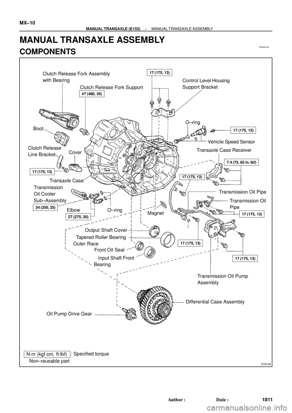
MX052±02
Z19124
Clutch Release Fork Assembly
with Bearing
Clutch Release Fork SupportControl Level Housing
Support Bracket
Boot�O±ring
Vehicle Speed Sensor
Transaxle Case Receiver Clutch Release
Line BracketCover
Transaxle Case
Transmission Oil
Pipe Transmission
Oil Cooler
Sub±Assembly
Elbow�O±ring
Magnet
�
Transmission Oil Pump
Assembly
Differential Case Assembly
Oil Pump Drive Gear�Output Shaft Cover
�Tapered Roller Bearing
Outer Race
�Front Oil Seal
�Input Shaft Front
Bearing
N´m (kgf´cm, ft´lbf): Specified torque
�Non±reusable part
47 (480, 35)
17 (175, 13)
17 (175, 13)
17 (175, 13)
17 (175, 13)
17 (175, 13)
7.4 (75, 65 in.´lbf)
17 (175, 13)
27 (275, 20)
34 (350, 25)
17 (175, 13)
Transmission Oil Pipe MX±10
± MANUAL TRANSAXLE (E153)MANUAL TRANSAXLE ASSEMBLY
1811 Author�: Date�:
MANUAL TRANSAXLE ASSEMBLY
COMPONENTS
Page 3815 of 4770
MANUAL TRANSAXLE ASSEMBLY
MX±13
1814 Author�: Date�:
DISASSEMBLY
1. REMOVE RELEASE FORK AND BEARING
2. REMOVE BACK±UP LIGHT SWITCH WITH GASKET")
MX053±02
Q05816
FIPG
Q00449
± MANUAL TRANSAXLE (E153)MANUAL TRANSAXLE ASSEMBLY
MX±13
1814 Author�: Date�:
DISASSEMBLY
1. REMOVE RELEASE FORK AND BEARING
2. REMOVE BACK±UP LIGHT SWITCH WITH GASKET
Torque: 40 N´m (410 kgf´cm, 30 ft´lbf)
3. REMOVE BOLT AND VEHICLE SPEED SENSOR
Torque: 17 N´m (175 kgf´cm, 13 ft´lbf)
4. REMOVE NO.2 SELECTING BELLCRANK WITH SE-
LECTING BELLCRANK SUPPORT
Remove the 2 bolts and No.2 selecting bellcrank with the se-
lecting bellcrank support.
Sealant:
Part No. 08833 ± 00080, THREE BOND 1344, LOCTITE
242 or equivalent
Torque: 20 N´m (200 kgf´cm, 14 ft´lbf)
5. REMOVE SHIFT AND SELECT LEVER SHAFT LOCK
BOLT WITH GASKET
Torque: 49 N´m (500 kgf´cm, 36 ft´lbf)
6. REMOVE SHIFT AND SELECT LEVER SHAFT AS-
SEMBLY WITH GASKET
Remove the 4 bolts, shift and select lever shaft assembly and
gasket.
Sealant:
Part No. 08833 ± 00080, THREE BOND 1344, LOCTITE
242 or equivalent
Torque: 20 N´m (200 kgf´cm, 14 ft´lbf)
7. REMOVE TRANSMISSION CASE COVER
Remove the 10 bolts and transmission case cover.
FIPG:
Part No. 08826 ± 00090, THREE BOND 1281 or equiva-
lent
Torque: 29 N´m (300 kgf´cm, 22 ft´lbf)
8. REMOVE BREATHER PLUG WITH GASKET
Torque: 49 N´m (500 kgf´cm, 36 ft´lbf)
9. REMOVE OUTPUT SHAFT LOCK NUT
(a) Unstake the lock nut.
(b) Engage the gear double meshing.
(c) Remove the lock nut.
Torque: 123 N´m (1,250 kgf´cm, 90 ft´lbf)
(d) Disengage the gear double meshing.
10. REMOVE NO.3 HUB SLEEVE AND NO.3 SHIFT FORK
(a) Remove the No.3 shift fork set bolt.
Torque: 24 N´m (240 kgf´cm, 17 ft´lbf)
(b) Remove the No.3 hub sleeve and No.3 shift fork.