Page 3844 of 4770
MX05H±01
Z17560
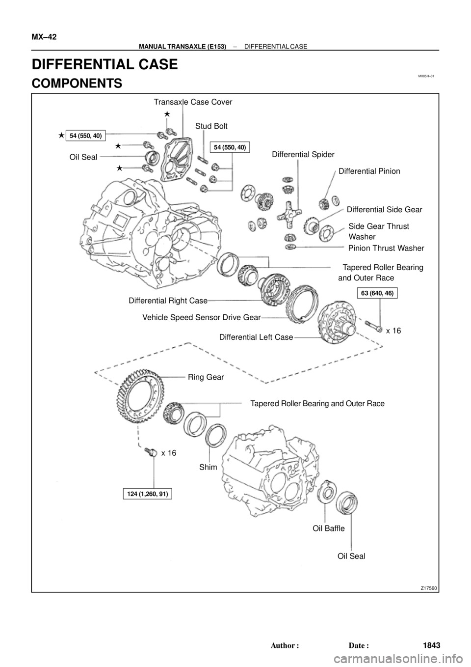
Transaxle Case Cover
Stud Bolt �
54 (550, 40)
�54 (550, 40)
�
�Oil Seal
�Differential Spider
Differential Pinion
Differential Side Gear
Side Gear Thrust
Washer
Pinion Thrust Washer
�Tapered Roller Bearing
and Outer Race
63 (640, 46)
x 16 Differential Right Case
Vehicle Speed Sensor Drive Gear
Differential Left Case
Ring Gear
x 16�Tapered Roller Bearing and Outer Race
Shim
124 (1,260, 91)
Oil Baffle
�Oil Seal MX±42
± MANUAL TRANSAXLE (E153)DIFFERENTIAL CASE
1843 Author�: Date�:
DIFFERENTIAL CASE
COMPONENTS
Page 3845 of 4770
DIFFERENTIAL CASE
MX±43
1844 Author�: Date�:
DISASSEMBLY
1. REMOVE TAPERED ROLLER BEARING
Using SST, remove the left and")
MX05I±03
Q05166
SST
Z00281
Matchmarks
Z00284
Z00286
± MANUAL TRANSAXLE (E153)DIFFERENTIAL CASE
MX±43
1844 Author�: Date�:
DISASSEMBLY
1. REMOVE TAPERED ROLLER BEARING
Using SST, remove the left and right bearings.
SST 09950±40011
2. REMOVE RING GEAR
(a) Place matchmarks on both the differential case and ring
gear.
(b) Remove the 16 bolts.
(c) Using a plastic hammer, tap the ring gear and remove it.
3. DISASSEMBLE DIFFERENTIAL CASE
(a) Place matchmarks on the differential right and left cases.
(b) Using a torx wrench (T50), remove the 16 torx screws.
(c) Using a plastic hammer, tap the differential left case.
(d) Remove the vehicle speed sensor drive gear from the dif-
ferential right case.
(e) Remove the 2 differential side gears, side gear thrust
washers, 4 differential pinions and pinion thrust washers
from the differential left case.
4. Transmission Case Side:
IF NECESSARY, REPLACE OIL SEAL AND TAPERED
ROLLER BEARING OUTER RACE
(a) Using a screwdriver, remove the oil seal.
(b) Remove the oil baffle.
(c) Using a brass bar and hammer, drive out the bearing out-
er race lightly and evenly.
(d) Remove the shim.
(e) Install the shim. (See page MX±42)
HINT:
First select and install a shim of less thickness than before.
Page 3848 of 4770
DIFFERENTIAL CASE
1847 Author�: Date�:
REASSEMBLY
1. ASSEMBLE DIFFERENTIAL CASE
HINT:
Coat all of the sliding and rotating surfac")
MX05J±01
Z00295
Z00296
Z00297
Z00298
MX±46
± MANUAL TRANSAXLE (E153)DIFFERENTIAL CASE
1847 Author�: Date�:
REASSEMBLY
1. ASSEMBLE DIFFERENTIAL CASE
HINT:
Coat all of the sliding and rotating surfaces with gear oil before
reassembly.
(a) Install the thrust washer to the side gear.
(b) Install the 4 pinions and thrust washers to the spider.
(c) Install the side gear and spider with the 4 pinions to the
differential left case.
(d) Using a dial indicator, measure the backlash of the pinion
gear while holding the differential left case.
Standard backlash:
0.05 ± 0.20 mm (0.0020 ± 0.0079 in.)
HINT:
Push the pinion gear and spider with the 4 pinions to the differ-
ential left case.
(e) Install the side gear and spider with the 4 pinions to the
right side of the differential case. Check the side gear
backlash.
(f) Refer to the table below, and select the thrust washer
which will ensure that the backlash is within the specifica-
tion. Try to select a washer of the same size.
Thickness mm (in.)Thickness mm (in.)
0.80 (0.0315)1.20 (0.0472)
0.90 (0.0354)1.30 (0.0512)
1.00 (0.0394)1.40 (0.0551)
1.10 (0.0433)±
(g) Install the vehicle speed sensor drive gear.
Page 3860 of 4770
± PREPARATIONENGINE MECHANICAL (1MZ±FE)
PP±9
61 Author�: Date�:
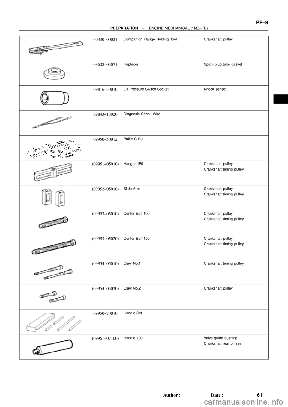
09330±00021Companion Flange Holding ToolCrankshaft pulley
09608±03071ReplacerSpark plug tube gasket
09816±30010Oil Pressure Switch SocketKnock sensor
09843±18020Diagnosis Check Wire
09950±50012Puller C Set
(09951±05010)Hanger 150Crankshaft pulley
Crankshaft timing pulley
(09952±05010)Slide ArmCrankshaft pulley
Crankshaft timing pulley
(09953±05010)Center Bolt 100Crankshaft pulley
Crankshaft timing pulley
(09953±05020)Center Bolt 150Crankshaft pulley
Crankshaft timing pulley
(09954±05010)Claw No.1Crankshaft timing pulley
(09954±05020)Claw No.2Crankshaft pulley
09950±70010Handle Set
(09951±07100)Handle 100Valve guide bushing
Crankshaft rear oil seal
Page 3868 of 4770
PP1WB±02
± PREPARATIONSFI (5S±FE)
PP±17
69 Author�: Date�:
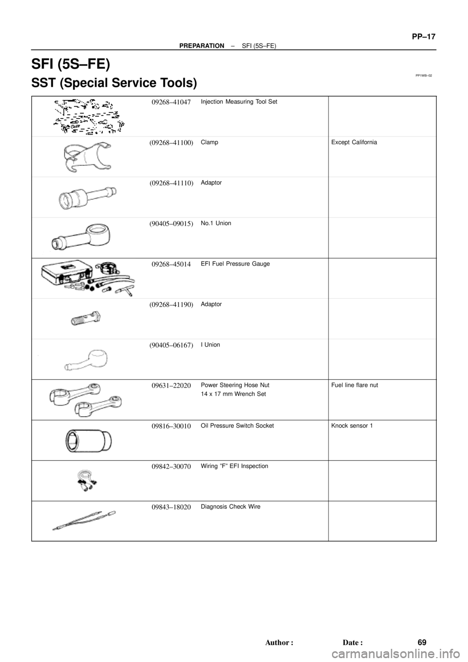
SFI (5S±FE)
SST (Special Service Tools)
09268±41047Injection Measuring Tool Set
(09268±41100)ClampExcept California
(09268±41110)Adaptor
(90405±09015)No.1 Union
09268±45014EFI Fuel Pressure Gauge
(09268±41190)Adaptor
(90405±06167)I Union
09631±22020Power Steering Hose Nut
14 x 17 mm Wrench SetFuel line flare nut
09816±30010Oil Pressure Switch SocketKnock sensor 1
09842±30070Wiring ºFº EFI Inspection
09843±18020Diagnosis Check Wire
Page 3871 of 4770
PP1WW±01
PP±20
± PREPARATIONSFI (1MZ±FE)
72 Author�: Date�:
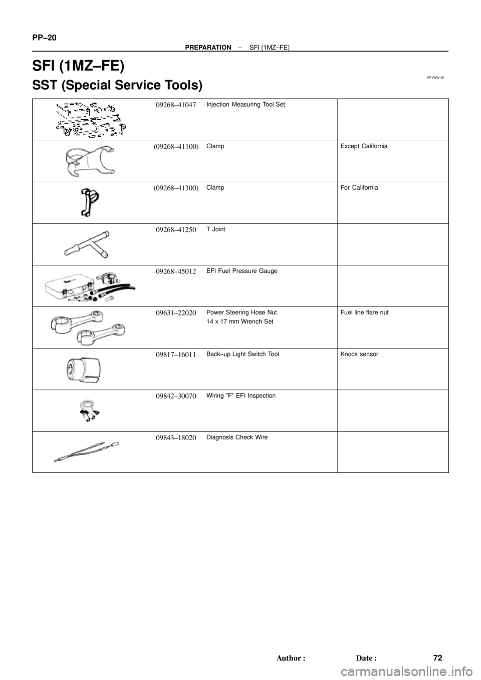
SFI (1MZ±FE)
SST (Special Service Tools)
09268±41047Injection Measuring Tool Set
(09268±41100)ClampExcept California
(09268±41300)ClampFor California
09268±41250T Joint
09268±45012EFI Fuel Pressure Gauge
09631±22020Power Steering Hose Nut
14 x 17 mm Wrench SetFuel line flare nut
09817±16011Back±up Light Switch ToolKnock sensor
09842±30070Wiring ºFº EFI Inspection
09843±18020Diagnosis Check Wire
Page 3950 of 4770
PP1XL±01
± PREPARATIONSUPPLEMENTAL RESTRAINT SYSTEM
PP±99
151 Author�: Date�:
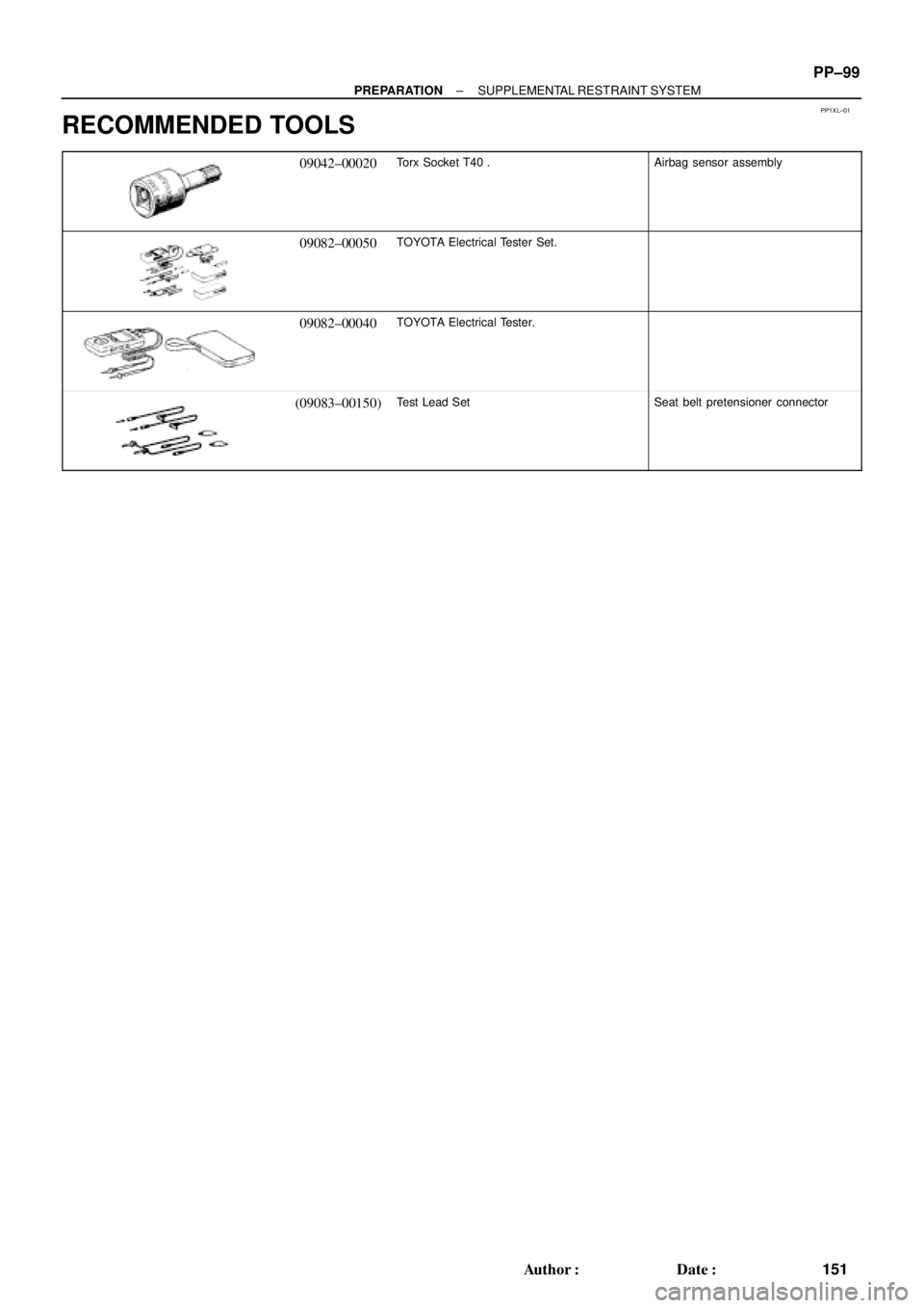
RECOMMENDED TOOLS
09042±00020Torx Socket T40 .Airbag sensor assembly
09082±00050TOYOTA Electrical Tester Set.
09082±00040TOYOTA Electrical Tester.
(09083±00150)Test Lead SetSeat belt pretensioner connector
Page 3977 of 4770

SS±15
178 Author�: Date�:
No.2 RH engine mounting stay x No.2 Generator bracket6465047
RH engine mounting stay x Water outlet3232023
RH engine mou")
± SERVICE SPECIFICATIONSENGINE MECHANICAL (1MZ±FE)
SS±15
178 Author�: Date�:
No.2 RH engine mounting stay x No.2 Generator bracket6465047
RH engine mounting stay x Water outlet3232023
RH engine mounting stay x Engine moving control rod3232023
RH engine mounting stay x No.2 RH engine mounting bracket3232023
Front engine mounting insulator x Front frame
TMC made
TMMK made Silver color bolt
Green color bolt
80
44
66820
450
67059
32
48
Engine mounting absorber x Front frame4849035
Engine mounting absorber x Transaxle4849035
Rear engine mounting insulator x Front frame6667048
LH engine mounting insulator x Transaxle6465047
PS pump x PS pump bracket4344031
A/C compressor x Housing bracket2525018
A/C compressor x No.1 oil pan2525018
Generator adjusting bar x Drive belt adjusting bar bracket1818513
Main bearing cap x Cylinder block 12 pointed head bolt 1st
2nd
6 pointed head bolt22
Turn 90°
27225
Turn 90°
27516
Turn 90°
20
Connecting rod cap x Connecting rod 1st
2nd24.5
Turn 90°250
Turn 90°18
Turn 90°
Rear oil seal retainer x Cylinder block88069 in.´lbf
EGR cooler x Cylinder block99078 in.´lbf
Engine coolant drain union x Cylinder block3940029
Water seal plate x Cylinder block1818013
Oil filter union x Cylinder block3031022
Water inlet housing x Cylinder block88069 in.´lbf
Knock sensor x Cylinder block3940029
No.2 idler pulley bracket x Cylinder block2829021
A/C compressor housing bracket x Cylinder block2525018
Generator bracket x Cylinder block4344032
Drive plate x Crankshaft8385061
Flywheel x Crankshaft8385061
Front exhaust pipe support bracket x No.1 oil pan2121015
Front exhaust pipe x Exhaust manifold6263046
Front exhaust pipe x Center exhaust pipe5657041
Center exhaust pipe x Tailpipe5657041
Front exhaust pipe bracket x Sub frame3333024
Front exhaust pipe support bracket x Front exhaust pipe stay3333024
Heated oxygen sensor x Center exhaust pipe4445033