Page 3714 of 4770
± INTRODUCTIONTERMS
IN±43
43 Author�: Date�:
TCMTransmission Control ModuleTransmission ECU, ECT ECU
TPThrottle PositionThrottle Position
TRTransmission Range±
TVVThermal Vacuum ValveBimetallic Vacuum Switching Valve (BVSV)
Thermostatic Vacuum Switching Valve (TVSV)
TWCThree±Way Catalytic Converter
Three±Way Catalytic (TWC)
Manifold Converter
CC
RO
TWC+OCThree±Way + Oxidation Catalytic ConverterCCR + CCo
VA FVolume Air FlowAir Flow Meter
VRVoltage RegulatorVoltage Regulator
VSSVehicle Speed SensorVehicle Speed Sensor
WOTWide Open ThrottleFull Throttle
WU±OCWarm Up Oxidation Catalytic Converter±
WU±TWCWarm Up Three±Way Catalytic Converter±
3GRThird Gear±
4GRFourth Gear±
Page 3719 of 4770
B06345
No.2 Timing Belt Cover
No.1 Timing Belt Cover* Gasket
Wire
ClampGeneratorGenerator Wire
Generator Connector
Crankshaft Pulley
No.2 Idler Pulley
Oil Pump Pulley
Crankshaft
Timing Pulley
Crankshaft Position SensorTiming Belt Guide
Wire ClampWire
Clamp
Timing Belt
Clamp
No.1 Idler Pulley
Tension Spring � GasketClamp
� Gasket
� GasketHigh±Tension Cord
Spark Plug
Oil Strainer
Drain Plug
N´m (kgf´cm, ft´lbf): Specified torque
� Non±reusable partx 17
* Gasket
* Replace only if damagedOil Pump
x 10
8.8 (90, 78 in.´lbf)5.4 (55, 48 in.´lbf)
5.4 (55, 48 in.´lbf)
24 (245, 18)
42 (425, 31)
108 (1,100, 80)
18 (180, 13)
42 (425, 31)
Oil Pan
± LUBRICATION (5S±FE)OIL PUMP
LU±5
1651 Author�: Date�:
Page 3739 of 4770
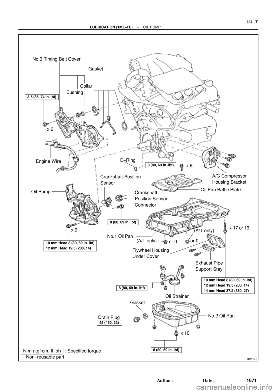
B04401
N´m (kgf´cm, ft´lbf) : Specified torque
� Non±reusable partNo.3 Timing Belt Cover
Gasket
BushingCollar
A/C Compressor
Housing Bracket
Oil Pan Baffle Plate
Crankshaft
Position Sensor
Connector Crankshaft Position
Sensor
Oil PumpEngine Wire
Flywheel Housing
Under Cover
Exhaust Pipe
Support Stay
Oil Strainer
No.2 Oil Pan
x 10x 6
x 9� O±Ring
No.1 Oil Pan
� Gasket
Drain Plug
8.5 (85, 74 in.´lbf)
8 (80, 69 in.´lbf)
8 (80, 69 in.´lbf)
10 mm Head 8 (80, 69 in.´lbf)
12 mm Head 19.5 (200, 14)
10 mm Head 8 (80, 69 in.´lbf)
12 mm Head 19.5 (200, 14)
14 mm Head 37.2 (380, 27)
8 (80, 69 in.´lbf)
45 (460, 33)
8 (80, 69 in.´lbf)
x 6
x 17 or 19
(A/T only)(A/T only)or 0or 0
± LUBRICATION (1MZ±FE)OIL PUMP
LU±7
1671 Author�: Date�:
Page 3742 of 4770
OIL PUMP
1674 Author�: Date�:
(b) Insert the blade of SST between the No.1 and No.2 oil
pans, and cut off applied sealer an")
P12716
SST
SST
P18802
B04136
B04137
P20050Pry LU±10
± LUBRICATION (1MZ±FE)OIL PUMP
1674 Author�: Date�:
(b) Insert the blade of SST between the No.1 and No.2 oil
pans, and cut off applied sealer and remove the No.1 oil
pan.
SST 09032±00100
NOTICE:
�Be careful not to the damage the No.2 oil pan contact
surface of the No.1 oil pan.
�Be careful not to damage the No.2 oil pan flange.
14. REMOVE OIL STRAINER
Remove the bolt, 2 nuts, oil strainer and gasket.
15. REMOVE NO.1 OIL PAN
(a) Remove the 2 bolts, exhaust pipe support stay and fly-
wheel housing under cover.
(b) Remove the 19 bolts (or 17 bolts and 2 nuts).
(c) Using a screwdriver, remove the oil pan by prying the por-
tions between the cylinder block and oil pan.
NOTICE:
Be careful not to damage the contact surfaces of the cylin-
der block and oil pan.
16. REMOVE BAFFLE PLATE FROM NO.1 OIL PAN
17. REMOVE CRANKSHAFT POSITION SENSOR
18. REMOVE OIL PUMP
(a) Remove the 9 bolts.
(b) Remove the oil pump by prying a screwdriver between the
oil pump and main bearing cap.
(c) Remove the O±ring.
Page 3748 of 4770
P12694
LU±16
± LUBRICATION (1MZ±FE)OIL PUMP
1680 Author�: Date�:
(d) Engage the spline teeth of the oil pump drive gear with the
large teeth of the crankshaft, and slide the oil pump on the
crankshaft.
(e) Install the oil pump with the 9 bolts. Uniformly tighten the
bolts in several passes.
Torque:
10 mm head: 8 N´m (80 kgf´cm, 69 in.´lbf)
12 mm head: 19.5 N´m (200 kgf´cm, 14 ft´lbf)
2. INSTALL CRANKSHAFT POSITION SENSOR
3. INSTALL BAFFLE PLATE TO NO.1 OIL PAN
Torque: 8 N´m (80 kgf´cm, 69 in.´lbf)
4. INSTALL NO.1 OIL PAN
(a) Remove any old packing (FIPG) material and be careful
not to drop any oil on the contact surfaces of the oil pan,
oil pump and cylinder block.
�Using a razor blade and gasket scraper, remove all
the old packing (FIPG) material from the gasket sur-
faces and sealing grooves.
�Thoroughly clean all components to remove all the
loose material.
�Using a non±residue solvent, clean both sealing
surfaces.
Page 3762 of 4770

MX04C±01
Q09998
Hood
ClipCruise Control Actuator
Control Cable
Clutch Line
Bracket
Clutch Release CylinderWasher
RH Drive Shaft
Snap Ring
RH Stiffener
Plate
Ground Cable
Starter
Battery
Snap Ring
LH Drive Shaft�
RH Fender Apron
Seal
LH Stiffener Plate
Manifold StayTransaxle Back±Up Light Switch
Connector
Rear End Plate with Oil Pan
InsulatorAir Cleaner
Case Assembly
with Air Hose
Vehicle Speed Sensor
Connector
No.1 Fuel Tube Protector Engine LH
Mounting Insulator
with Bracket
Rear RH Suspension Member Brace
PS Gear Assembly
Lock Cap
Rear LH Suspension Member Brace Manifold StayClip
LH Fender Apron
Seal
Suspension Member with
Lower Suspension Arm
Front RH Suspension
Member BraceStabilizer Bar Link
Front Exhaust PipeCotter Pin
RH Fender
Liner
LH Fender Liner
Exhaust Pipe BracketNo.1 Exhaust Pipe
Support Bracket
: Specified torque
Non±reusable partGasket w/ Cruise Control:
�
�
�
Cotter Pin
�
Hole
Plug
�
�
Engine Rear Side Shutter PlateHold±Down
Clamp
Hole
Plug
12 (120, 9)
13 (130, 9)
46 (470, 34)
39 (400, 29)
6.9 (70, 61 in.´lbf)
14 (145, 10)
12 (120, 9)
39 (400, 29)
39 (400, 29)
64 (650, 47)
56 (570, 41)
37 (380, 27)
9.3 (95, 82 in.´lbf)
42 (425, 31)
32 (330, 24)
Silver Bolt: 44 (450, 33)
Green Bolt: 66 (670, 48)
62 (630, 46)
64 (650, 47)
64 (650, 47)
37 (380, 27)
181 (1,850, 134)
181 (1,850, 134)
181 (1,850, 134)
36 (370, 27)
10 (100, 7)
32 (330, 24)19 (195, 14)
49 (500, 36)
294 (3,000, 217)
Silver Bolt: 44 (450, 33)
Green Bolt: 66 (670, 48)
36 (370, 27)66 (670, 48)
39 (400, 29)
127 (1,300, 94)
33 (330, 24)
33 (330, 24)
19 (195, 14)
80 (820, 59)
Gasket�
�� �
Steering Return Pipe
Front LH
Suspension
Member Brace
N´m (kgf´cm, ft´lbf)
± MANUAL TRANSAXLE (S51)MANUAL TRANSAXLE UNIT
MX±3
1853 Author�: Date�:
MANUAL TRANSAXLE UNIT
COMPONENTS
Page 3763 of 4770
MANUAL TRANSAXLE UNIT
1854 Author�: Date�:
REMOVAL
1. REMOVE HOOD
HINT:
At the time of installation, please refer to the followi")
MX04D±01
Q09982
Q09999
BA
Q10000
Q10001
MX±4
± MANUAL TRANSAXLE (S51)MANUAL TRANSAXLE UNIT
1854 Author�: Date�:
REMOVAL
1. REMOVE HOOD
HINT:
At the time of installation, please refer to the following item.
Adjust the hood.
(See page BO±10)
2. REMOVE BATTERY AND AIR CLEANER CASE AS-
SEMBLY WITH AIR HOSE
3. w/ Cruise Control:
REMOVE CRUISE CONTROL ACTUATOR
(a) Disconnect the cruise control actuator connector.
(b) Remove the 3 bolts and cruise control actuator with the
bracket.
Torque: 13 N´m (130 kgf´cm, 9 ft´lbf)
4. REMOVE STARTER
(a) Disconnect the connector and wire from the starter.
(b) Remove the 2 bolts and starter.
Torque: 39 N´m (400 kgf´cm, 29 ft´lbf)
5. DISCONNECT CLUTCH RELEASE CYLINDER
(a) Remove the 2 bolts and disconnect the release cylinder.
Torque: 12 N´m (120 kgf´cm, 9 ft´lbf)
(b) Remove the 2 set bolts of the clutch line bracket.
Torque:
Bolt A: 12 N´m (120 kgf´cm, 9 ft´lbf)
Bolt B: 6.9 N´m (70 kgf´cm, 61 in.´lbf)
6. DISCONNECT GROUND CABLE
Remove the set bolt of the ground cable from the transaxle.
7. REMOVE MANIFOLD STAY
Remove the 2 bolts and stay.
Torque: 42 N´m (425 kgf´cm, 31 ft´lbf)
8. DISCONNECT VEHICLE SPEED SENSOR AND
BACK±UP LIGHT SWITCH CONNECTORS
9. DISCONNECT CONTROL CABLE
(a) Remove the 2 clips and washers.
(b) Remove the 2 clips from the cables.
Page 3768 of 4770

MX04F±02
Z19123
Transmission Case Cover5th Driven GearRear Bearing Retainer
No.3 Shift Fork N0.3 Hub Sleeve No.3 Clutch Hub Assembly Needle Roller BearingRelease ForkTransmission
CaseDifferential Side
Bearing Retainer
Transmission
Case Protector Straight Screw Plug
Shift and Select Lever
Assembly
Selecting Bellcrank Back±UP
Light SwitchLock Ball
Assembly Release Bearing
Retainer
Vehicle
Speed Sensor
Release
BearingReverse
Restrict Pin�
O±Ring �Shim
x 6 Slotted
Spring Pin
Gasket
Clutch Release Fork
Support
x 17
Snap RingLock Nut Filler Plug
Lock Boltx 5
Spacer
5th Gear
x 8 Boot
�
Gasket �
Gasket �Drain Plug
Snap Ring�
�
�
� �Non±reusable part
Precoated part: Specified torque
N´m (kgf´cm, ft´lbf)
5.4 (55, 48 in.´lbf)
13 (130, 9)
123 (1,250, 90)�
37 (375, 27)29 (300, 22)�
44 (450, 33)
18 (185, 13)
18 (185, 13)
42 (430, 31)
29 (300, 22)
29 (300, 22)
49 (500, 36)
39 (400, 29)
18 (185, 13)
29 (300, 22)
7.4 (75, 65 in.´lbf)
37 (380, 27)
± MANUAL TRANSAXLE (S51)MANUAL TRANSAXLE ASSEMBLY
MX±9
1859 Author�: Date�:
MANUAL TRANSAXLE ASSEMBLY
COMPONENTS