Page 3660 of 4770

Replace the camshaft position sensor.CHECK RESISTANCE OF CAMSHAFT POSITION SENSOR
Resistance: Cold Hot
835 ± 1,400 W1,060 ± 1,645 W
CHECK IGT SIGNAL FROM ECM
CHECK RESISTANCE OF CRANKSHAFT POSITION SENSOR
Resistance: Cold Hot
1,630 ± 2,740 W2,065 ± 3,225 W
TRY ANOTHER IGNITERReplace the crankshaft position sensor.
Check wiring between ECM and igniter, and
then try another ECM.
OK
OK
OKBAD
BAD
BAD
OK
Continued from the previous page
DENSO made:
Wabash made:1,690 ± 2,560 W2,145 ± 3,010 W
B00848
P24453
WRONG
CORRECT
P24457
IG±2
± IGNITION (1MZ±FE)IGNITION SYSTEM
1696 Author�: Date�:
2. INSPECT HIGH±TENSION CORDS
(a) Remove the V±bank cover.
(b) Disconnect the high±tension cords from the spark plugs.
(1) Using needle±nose pliers, disconnect the cord
clamp from the engine wire protector.
(2) Disconnect the high±tension cords from the spark
plugs.
NOTICE:
Pulling on or bending the cords may damage the conductor
inside.
(3) Disconnect the high±tension cords from the clamp.
(c) Disconnect the high±tension cords from the ignition coils.
(1) Using a screwdriver, lift up the lock claw and discon-
nect the holder from the ignition coils.
(2) Disconnect the high±tension cord at the grommet.
NOTICE:
�Pulling on or bending the cords may damage the con-
ductor inside.
�Do not wipe any of the oil from the grommet after the
high±tension cord is disconnected.
Page 3664 of 4770
IGNITION SYSTEM
1700 Author�: Date�:
(c) Using an ohmmeter, measure the primary coil resistance
between the positive (+) and")
S05622
Ohmmeter
B00849
Ohmmeter
S04599
Ohmmeter IG±6
± IGNITION (1MZ±FE)IGNITION SYSTEM
1700 Author�: Date�:
(c) Using an ohmmeter, measure the primary coil resistance
between the positive (+) and negative (±) terminals.
Primary coil resistance:
Cold0.70 ± 0.94 W
Hot0.85 ± 1.10 W
If the resistance is not as specified, replace the ignition coil.
(d) Using an ohmmeter, measure the secondary coil resis-
tance between the positive (+) and high±tension terminal.
Secondary coil resistance:
AISAN madeCold10.8 ± 14.9 kW
AISAN madeHot13.1 ± 17.5 kW
Diamond madeCold6.8 ± 11.7 kW
Diamond madeHot8.6 ± 13.7 kW
If the resistance is not as specified, replace the ignition coil.
(e) Connect the ignition coil connectors.
(f) Connect the high±tension cords to the ignition coils.
5. INSPECT CAMSHAFT POSITION SENSOR
(a) Disconnect the camshaft position sensor connector.
(b) Using an ohmmeter, measure the resistance between ter-
minals.
Resistance:
DENSO madeCold835 ± 1,400 W
DENSO madeHot1,060 ± 1,645 W
Wabash madeCold1,690 ± 2,560 W
Wabash madeHot2,145 ± 3,010 W
If the resistance is not as specified, replace the camshaft posi-
tion sensor.
(c) Connect the camshaft position sensor connector.
Page 3667 of 4770
S04589
IG02K±03
± IGNITION (1MZ±FE)CAMSHAFT POSITION SENSOR
IG±9
1703 Author�: Date�:
CAMSHAFT POSITION SENSOR
REMOVAL
REMOVE CAMSHAFT POSITION SENSOR
(a) Disconnect the camshaft position sensor connector.
(b) Remove the 2 bolts and camshaft position sensor.
Torque: 8 N´m (80 kgf´cm, 69 in.´lbf)
Page 3668 of 4770
IG02L±01
IG±10
± IGNITION (1MZ±FE)CAMSHAFT POSITION SENSOR
1704 Author�: Date�:
INSTALLATION
Installation is in the reverse order of removal. (See page IG±9)
Page 3669 of 4770
IG02M±03
P20105
± IGNITION (1MZ±FE)CRANKSHAFT POSITION SENSOR
IG±11
1705 Author�: Date�:
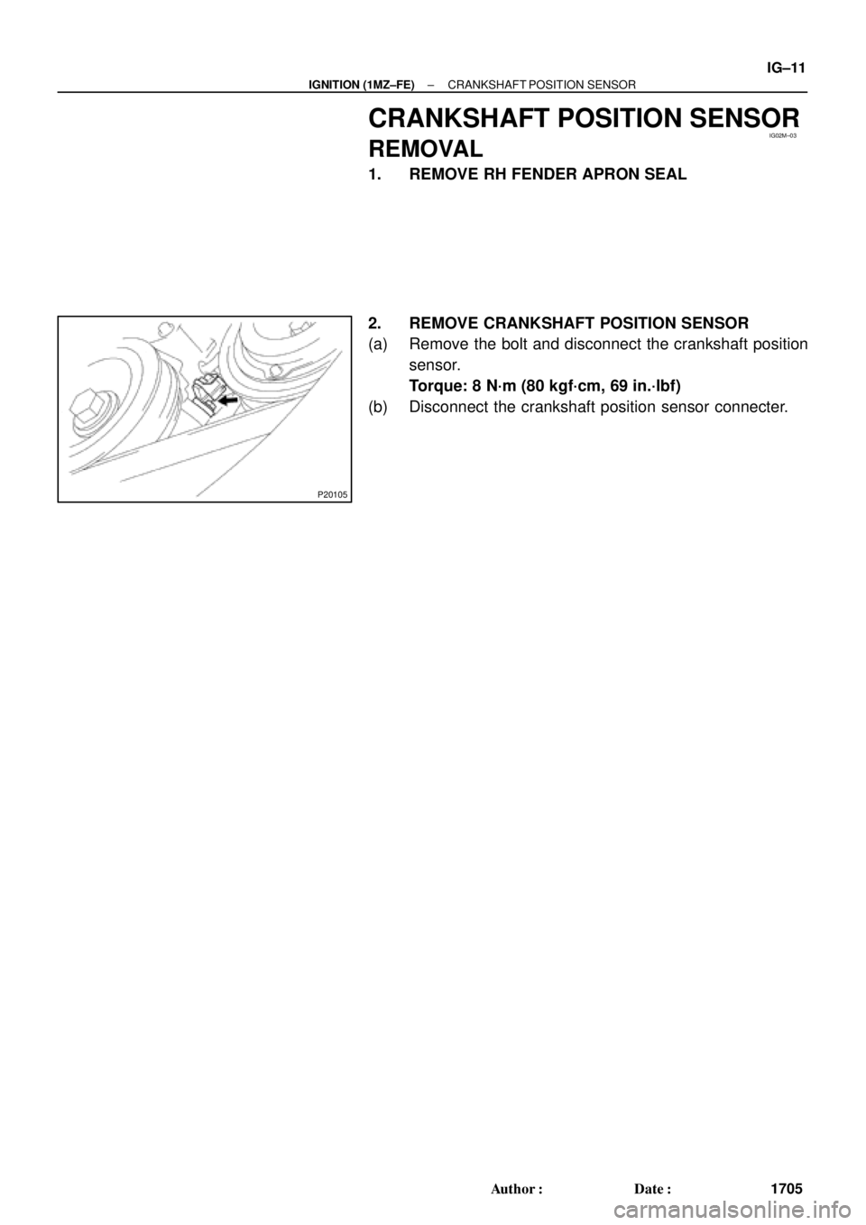
CRANKSHAFT POSITION SENSOR
REMOVAL
1. REMOVE RH FENDER APRON SEAL
2. REMOVE CRANKSHAFT POSITION SENSOR
(a) Remove the bolt and disconnect the crankshaft position
sensor.
Torque: 8 N´m (80 kgf´cm, 69 in.´lbf)
(b) Disconnect the crankshaft position sensor connecter.
Page 3670 of 4770
IG02N±03
P14244
Ohmmeter IG±12
± IGNITION (1MZ±FE)CRANKSHAFT POSITION SENSOR
1706 Author�: Date�:
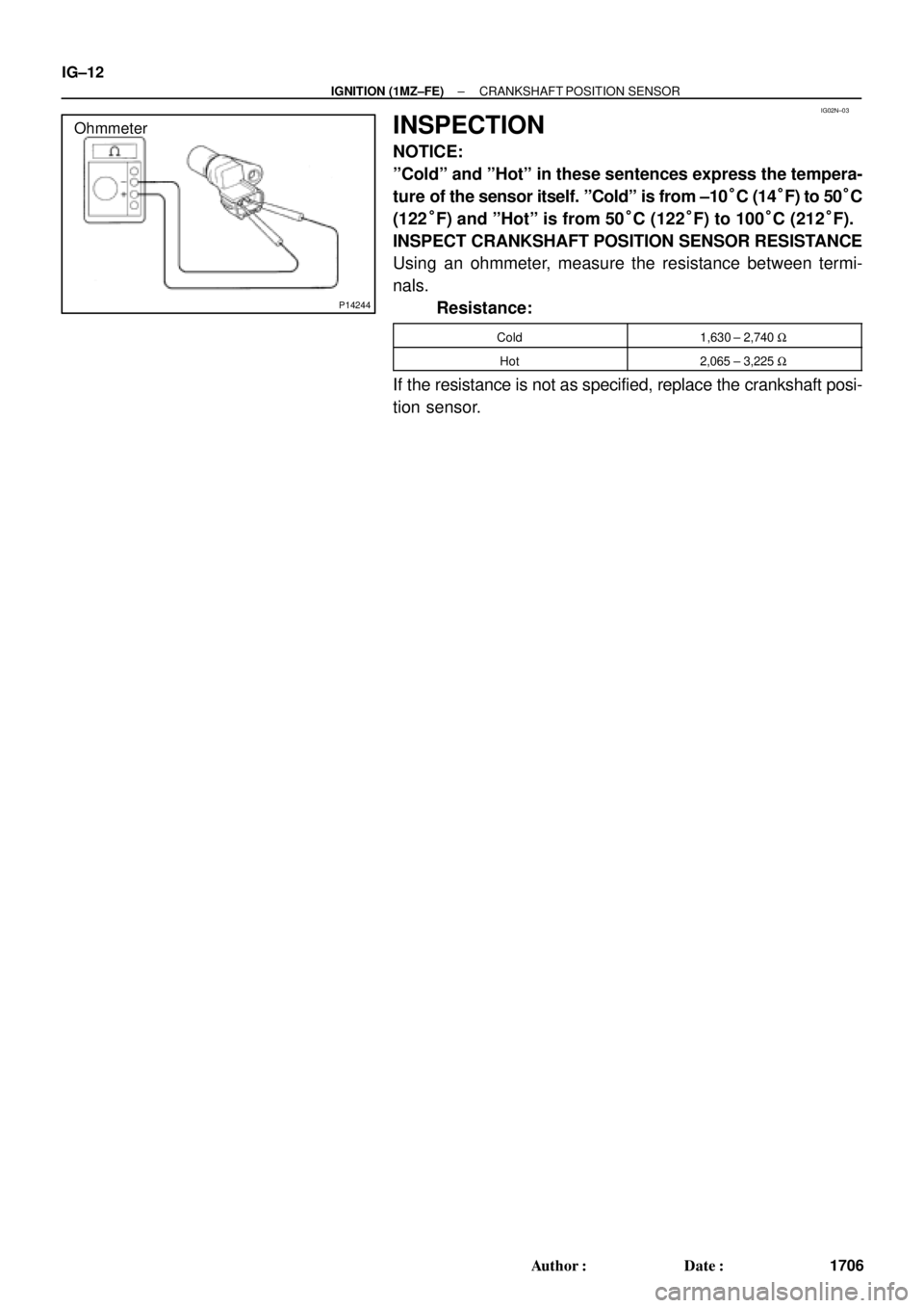
INSPECTION
NOTICE:
ºColdº and ºHotº in these sentences express the tempera-
ture of the sensor itself. ºColdº is from ±10°C (14°F) to 50°C
(122°F) and ºHotº is from 50°C (122°F) to 100°C (212°F).
INSPECT CRANKSHAFT POSITION SENSOR RESISTANCE
Using an ohmmeter, measure the resistance between termi-
nals.
Resistance:
Cold1,630 ± 2,740 W
Hot2,065 ± 3,225 W
If the resistance is not as specified, replace the crankshaft posi-
tion sensor.
Page 3671 of 4770
IG02O±01
± IGNITION (1MZ±FE)CRANKSHAFT POSITION SENSOR
IG±13
1707 Author�: Date�:
INSTALLATION
Installation is in the reverse order of removal. (See page IG±11)
Page 3677 of 4770
 Care must be taken when jacking up and supporting the
vehicle. Be sure to lift and support the")
IN0253
WRONG CORRECT
IN0252
WRONG CORRECT IN±6
± INTRODUCTIONREPAIR INSTRUCTIONS
6 Author�: Date�:
(k) Care must be taken when jacking up and supporting the
vehicle. Be sure to lift and support the vehicle at the prop-
er locations (See page IN±8).
�Cancel the parking brake on the level place and
shift the transmission in Neutral (or N position).
�When jacking up the front wheels of the vehicle at
first place stoppers behind the rear wheels.
�When jacking up the rear wheels of the vehicle at
first place stoppers before the front wheels.
�When either the front or rear wheels only should be
jacked up, set rigid racks and place stoppers in front
and behind the other wheels on the ground.
�After the vehicle is jacked up, be sure to support it
on rigid racks . It is extremely dangerous to do any
work on a vehicle raised on a jack alone, even for
a small job that can be finished quickly.
(l) Observe the following precautions to avoid damage to the
following parts:
(1) Do not open the cover or case of the ECU unless
absolutely necessary. (If the IC terminals are
touched, the IC may be destroyed by static electric-
ity.)
(2) To disconnect vacuum hoses, pull off the end, not
the middle of the hose.
(3) To pull apart electrical connectors, pull on the con-
nector itself, not the wires.
(4) Be careful not to drop electrical components, such
as sensors or relays. If they are dropped on a hard
floor, they should be replaced and not reused.
(5) When steam cleaning an engine, protect the elec-
tronic components, air filter and emission±related
components from water.
(6) Never use an impact wrench to remove or install
temperature switches or temperature sensors.
(7) When checking continuity at the wire connector, in-
sert the tester probe carefully to prevent terminals
from bending.
(8) When using a vacuum gauge, never force the hose
onto a connector that is too large. Use a step±down
adapter for adjustment. Once the hose has been
stretched, it may leak air.