Page 3475 of 4770
A07354
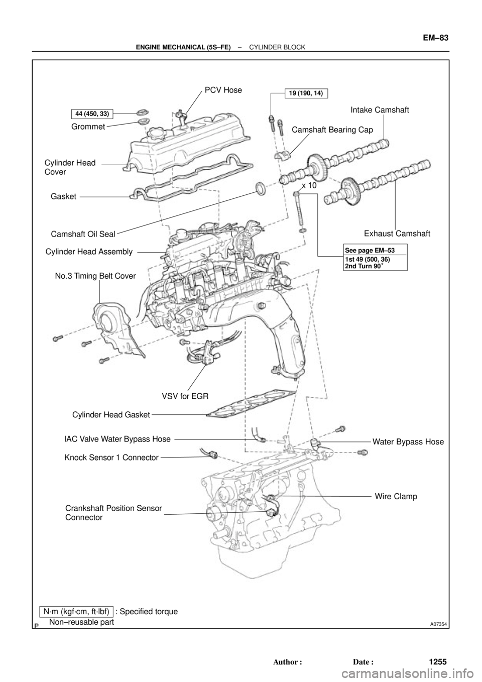
Grommet
Cylinder Head
Cover
Gasket
� Camshaft Oil Seal
Cylinder Head Assembly
No.3 Timing Belt Cover
Crankshaft Position Sensor
ConnectorWire Clamp Water Bypass Hose Exhaust Camshaft Intake Camshaft
Camshaft Bearing Cap PCV Hose
� Cylinder Head Gasket
IAC Valve Water Bypass Hose
Knock Sensor 1 Connector
N´m (kgf´cm, ft´lbf)
� Non±reusable part
44 (450, 33)
19 (190, 14)
VSV for EGR
: Specified torquex 10
1st 49 (500, 36)
2nd Turn 90° See page EM±53
± ENGINE MECHANICAL (5S±FE)CYLINDER BLOCK
EM±83
1255 Author�: Date�:
Page 3476 of 4770
A07367
Water Pump, Water Bypass Pipe
and Oil Cooler Assembly
Water Pump and Water
Bypass Pipe Assembly
(w/o Oil Cooler)
Union Bolt
Generator Drive Belt Adjusting Bar
Knock Sensor 1Oil Filter
Oil Dipstick
PS Pump
Bracket
Crankshaft Position Sensor Connector
Oil Pump
� Gasket x 10
Oil Strainer
Oil Pan
Drain Plug
N´m (kgf´cm, ft´lbf)
� Non±reusable partx 17 � Gasket
� Gasket � O±Ring
8.8 (90, 78 in.´lbf)5.4 (55, 48 in.´lbf)
5.4 (55, 48 in.´lbf)
� O±Ring
78.5 (800, 58)
w/ Oil Cooler
: Specified torque
Crankshaft
Front Oil
Seal �
EM±84
± ENGINE MECHANICAL (5S±FE)CYLINDER BLOCK
1256 Author�: Date�:
Page 3478 of 4770
CYLINDER BLOCK
1258 Author�: Date�:
DISASSEMBLY
1. INSTALL ENGINE TO ENGINE STAND FOR DIS-
ASSEMBLY
2. REMOVE TIMING BELT AND PULLEYS
(See pa")
EM0YW±01
S06011
1
3
2 EM±86
± ENGINE MECHANICAL (5S±FE)CYLINDER BLOCK
1258 Author�: Date�:
DISASSEMBLY
1. INSTALL ENGINE TO ENGINE STAND FOR DIS-
ASSEMBLY
2. REMOVE TIMING BELT AND PULLEYS
(See page EM±17)
3. REMOVE CYLINDER HEAD ASSEMBLY
(a) Remove the 3 bolts and No.3 timing belt cover.
(b) Remove the cylinder head cover.
(1) Disconnect the PCV hose from the intake manifold.
(2) Remove the 4 nuts, 4 grommets, head cover and
gasket.
(c) Remove the camshafts. (See page EM±33)
(d) Disconnect the knock sensor 1 connector.
(e) Disconnect the crankshaft position sensor connector.
(f) Disconnect the wire clamp from the generator drive belt
adjusting bar.
(g) Disconnect the IAC valve water bypass hose from the wa-
ter bypass pipe.
(h) Disconnect the water bypass hose (from the water by-
pass pipe) from the water outlet.
(i) Remove the bolt holding the VSV for EGR to the intake
manifold.
(j) Remove the 2 bolts holding the water bypass pipe to the
cylinder head.
(k) Remove the cylinder head assembly.
(See page EM±33)
4. REMOVE OIL DIPSTICK
5. REMOVE OIL PAN AND OIL PUMP
(a) Disconnect the crankshaft position sensor connector
from the generator drive belt adjusting bar.
(b) Remove the oil pan and oil pump. (See page LU±7)
6. REMOVE PS PUMP BRACKET
Remove the 3 bolts and pump bracket.
7. REMOVE KNOCK SENSOR 1 (See page SF±57)
8. REMOVE OIL FILTER (See page LU±2)
9. REMOVE WATER PUMP, WATER BYPASS PIPE AND
OIL COOLER (w/ OIL COOLER) ASSEMBLY
(a) w/ Oil Cooler:
Remove the nut and union bolt, and disconnect the oil
cooler. Remove the O±ring.
(b) Remove the bolt and generator drive belt adjusting bar.
(c) Remove the 3 bolts in the sequence shown, remove the
water pump, water bypass pipe, oil cooler (w/ oil cooler)
assembly and O±ring.
Page 3504 of 4770
CYLINDER BLOCK
1284 Author�: Date�:
(g) While pulling the center part of the engine balancer in the
direction of the arrow,")
S04614
1
Pull 53
426
P01477
Z19357
13
2 EM±112
± ENGINE MECHANICAL (5S±FE)CYLINDER BLOCK
1284 Author�: Date�:
(g) While pulling the center part of the engine balancer in the
direction of the arrow, uniformly tighten the 6 bolts in sev-
eral passes, in the sequence shown.
Torque: 49 N´m (500 kgf´cm, 36 ft´lbf)
(h) Recheck that the punch marks of the balance shafts are
aligned with the grooves of the No.2 housing.
14. CHECK AND ADJUST BACKLASH OF CRANKSHAFT
GEAR AND NO.1 BALANCE SHAFT GEAR
(See page EM±86)
15. INSTALL REAR OIL SEAL RETAINER
Install a new gasket and the retainer with the 6 bolts.
Torque: 13 N´m (130 kgf´cm, 9 ft´lbf)
16. INSTALL WATER PUMP, WATER BYPASS PIPE AND
OIL COOLER (w/ OIL COOLER) ASSEMBLY
(a) Install a new O±ring to the water pump cover.
(b) Install the water pump, water bypass pipe and oil cooler
(w/ oil cooler) assembly with the 3 bolts. Tighten the bolts
in the sequence shown.
Torque: 8.8 N´m (90 kgf´cm, 78 in.´lbf)
(c) Install the generator drive belt adjusting bar with the bolt.
Torque: 22 N´m (224 kgf´cm, 16 ft´lbf)
(d) w/ Oil Cooler:
Install the oil cooler. (See page LU±18)
17. INSTALL OIL FILTER (See page LU±2)
18. INSTALL KNOCK SENSOR 1 (See page SF±57)
19. INSTALL PS PUMP BRACKET
Install the PS pump bracket with the 3 bolts.
Torque: 43 N´m (440 kgf´cm, 32 ft´lbf)
20. INSTALL OIL PUMP AND OIL PAN
(a) Install the oil pump and oil pan. (See page LU±13)
(b) Install the crankshaft position sensor connector to the
generator drive belt adjusting bar.
21. INSTALL OIL DIPSTICK
22. INSTALL CYLINDER HEAD ASSEMBLY
(a) Install the cylinder head assembly. (See page EM±33)
(b) Install the 2 bolts holding the water bypass pipe to the cyl-
inder head.
Torque: 19 N´m (195 kgf´cm, 14 ft´lbf)
(c) Install the VSV for EGR to the cylinder head with the bolt.
(d) Connect the knock sensor 1 connector.
(e) Connect the crankshaft position sensor connector.
Page 3506 of 4770
EM08M±03
A07369
Heated Oxygen Sensor (Bank 1 Sensor 2)
HINT:
Before installing oxygen sensor, twist
sensor wire counterclockwise 3 and 1/2
turns.
After installing oxygen sensor, check that
sensor wire is not twisted. If it is twisted,
remove oxygen sensor and reinstall it.
Heat Insulator
Bracket
RingTailpipe
� Gasket
Center Exhaust Pipe
Heated Oxygen Sensor
(Bank 1 Sensor 2)
TWC (Except California)
Rear TWC (California)
Front Exhaust Pipe Bracket
StayBracket
N´m (kgf´cm, ft´lbf)
� Non±reusable part� Gasket
� Gasket
�Heat Insulator Heat Insulator
Heat Insulator
�
56 (570, 41)
44 (450, 32)
62 (630, 46)
56 (570, 41)
�Bracket
: Specified torqueRing �
�
19 (195, 14)
33 (330, 24)
33 (330, 24)
33 (330, 24)
EM±114
± ENGINE MECHANICAL (5S±FE)EXHAUST SYSTEM
1286 Author�: Date�:
EXHAUST SYSTEM
COMPONENTS
Page 3508 of 4770
CO/HC
1288 Author�: Date�:
If the CO/HC concentration dose not comply with regulations,
troubleshoot in the order given below.
See the table below for possible caus")
EM±2
± ENGINE MECHANICAL (1MZ±FE)CO/HC
1288 Author�: Date�:
If the CO/HC concentration dose not comply with regulations,
troubleshoot in the order given below.
See the table below for possible causes, then inspect and cor-
rect the applicable causes if necessary.
COHCProblemsCauses
NormalHighRough idle1. Faulty ignitions:
�Incorrect timin
g�Incorrect timing
�Fouled, shorted or improperly gapped plugs
�Open or crossed hi
gh±tension cords�Oen or crossed high±tension cords
2. Incorrect valve clearance
3 Leaky EGR valve
3 Leaky EGR valve
4.Leaky intake and exhaust valves
5.Leaky cylinder
LowHighRough idle1. Vacuum leaks:LowHighRough idle
(
Filtrating HC reading)
1. Vacuum leaks:
�PCV hose(Filtrating HC reading)�PCV hose
�EGR valve�EGR valve
�Intake manifold�Intake manifold
�Air intake chamber�Air intake chamber
�Throttle bodyThrottle body
�IAC valveIAC valve
�Brake booster lineBrake booster line
2. Lean mixture causing misfire
HighHighRough idle
(Black smoke from exhaust)1. Restricted air filter
2. Faulty SFI system
�Faulty pressure regulator
�Defective ECT sensor
�Faulty ECM
�Faulty injectors
�Faulty throttle position sensor
�Faulty MAF meter
Page 3524 of 4770
A01802
10 mm
Hexagon
Wrench
Plate Washer
P20026
SST EM±18
± ENGINE MECHANICAL (1MZ±FE)TIMING BELT
1304 Author�: Date�:
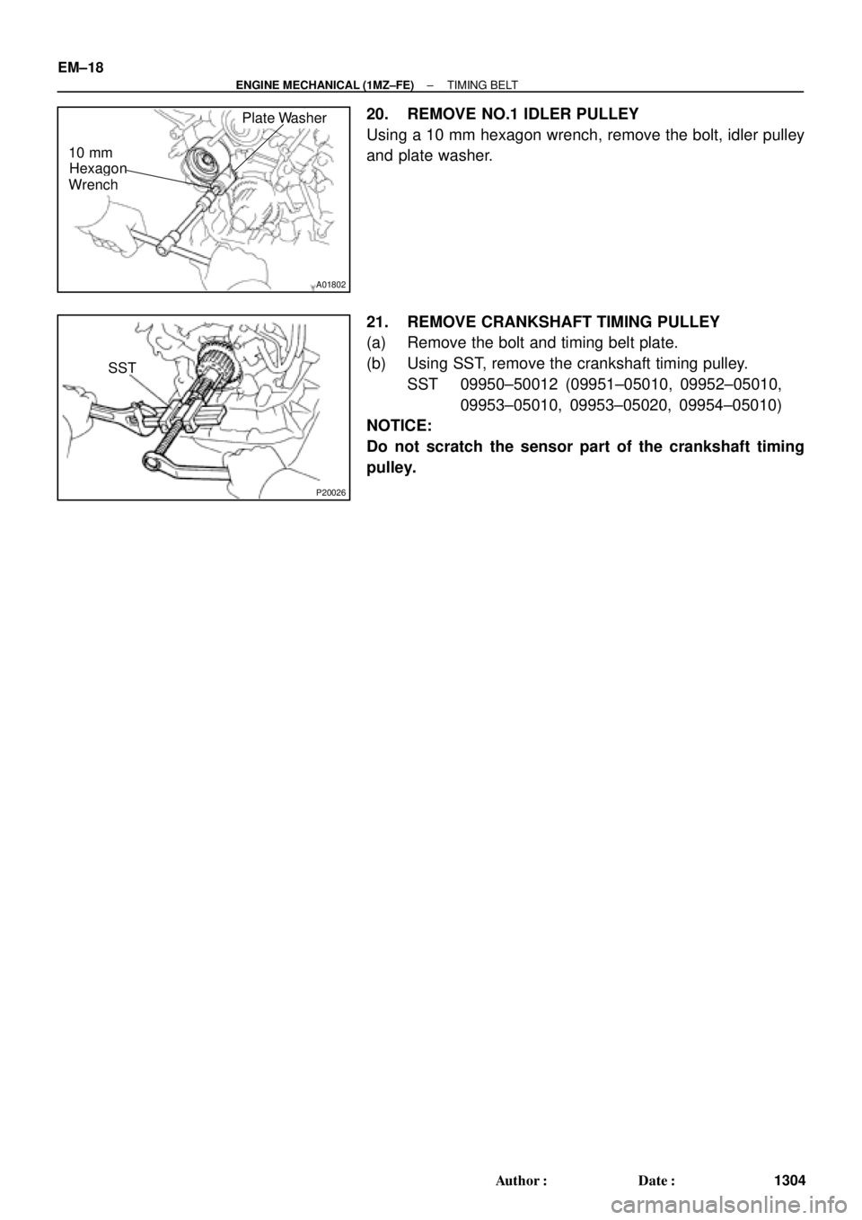
20. REMOVE NO.1 IDLER PULLEY
Using a 10 mm hexagon wrench, remove the bolt, idler pulley
and plate washer.
21. REMOVE CRANKSHAFT TIMING PULLEY
(a) Remove the bolt and timing belt plate.
(b) Using SST, remove the crankshaft timing pulley.
SST 09950±50012 (09951±05010, 09952±05010,
09953±05010, 09953±05020, 09954±05010)
NOTICE:
Do not scratch the sensor part of the crankshaft timing
pulley.
Page 3527 of 4770
TIMING BELT
EM±21
1307 Author�: Date�:
INSTALLATION
1. INSTALL CRANKSHAFT TIMING PULLEY
(a")
EM0YO±01
A05060
Inward
Sensor
A01802
10 mm
Hexagon
Wrench
Plate Washer
A05055
± ENGINE MECHANICAL (1MZ±FE)TIMING BELT
EM±21
1307 Author�: Date�:
INSTALLATION
1. INSTALL CRANKSHAFT TIMING PULLEY
(a) Align the pulley set key with the key groove of the timing
pulley, and slide on the timing pulley.
(b) Install the timing pulley, facing the sensor side inward.
NOTICE:
Do not scratch the sensor part of the crankshaft timing
pulley.
(c) Install the timing belt plate with the bolt.
Torque: 8 N´m (80 kgf´cm, 69 in.´lbf)
2. INSTALL NO.1 IDLER PULLEY
Adhesive: Part No. 08833±00080, THREE BOND 1344,
LOCTITE 242 or equivalent
(a) Using a 10 mm hexagon wrench, install the plate washer
and idler pulley with the pivot bolt.
Torque: 34 N´m (350 kgf´cm, 25 ft´lbf)
(b) Check that the pulley bracket moves smoothly.
3. INSTALL NO.2 IDLER PULLEY
(a) Install the idler pulley with the bolt.
Torque: 43 N´m (440 kgf´cm, 32 ft´lbf)
(b) Check that the idler pulley moves smoothly.
4. INSTALL RH CAMSHAFT TIMING PULLEY
(a) Face the flange side of the timing pulley outward.
(b) Align the knock pin on the camshaft with the knock pin
groove of the timing pulley, and slide on the timing pulley.

Union Bolt
Generator Drive Belt Adjusting Bar
Knock Sensor 1Oil Filter
Oil Dipst")

HINT:
Before installing oxygen sensor, twist
sensor wire counterclockwise 3 and 1/2
turns.
After installing oxygen sensor, check that
sensor wir")