Page 3377 of 4770
EC01W±03
B06721
VSV for Vapor
Pressure Sensor Vapor Pressure
SensorVacuum Surge
Tank
EGR Valve
Position
Sensor
A/F Sensor
(California A/T)
Heated Oxygen Sensor
(Bank 2 Sensor 1/
Except California A/T)
A/F Sensor
(California A/T)
Heated Oxygen
Sensor
(Bank 1 Sensor 1/
Except California A/T)
Heated Oxygen
Sensor
(Bank 1 Sensor 2) VCV
TWC VSV for EVAP
Fuel Tank
Charcoal
CanisterVSV for EGR
WU±TWC
(California A/T)
EVAP Service Port
Purge Line
Air Inlet Line
Air Drain Hose
WU±TWC
(California A/T)
EVAP Line
Vent Line
± EMISSION CONTROL (1MZ±FE)PARTS LAYOUT AND SCHEMATIC DRAWING
EC±3
1418 Author�: Date�:
DRAWING
Page 3379 of 4770
EC0AU±01
B01507
Vapor Pressure Sensor
ConnectorVapor Pressure SensorVSV Connector for Vapor
Pressure SensorEVAP Line Hose
Vent Line Hose
Air Inlet Line Hose
Purge Line Hose
Air Drain Hose
VSV for Vapor Pressure Sensor
39.2 (400, 29)
N´m (kgf´cm, ft´lbf) : Specified torqueCharcoal Canister
± EMISSION CONTROL (1MZ±FE)EVAPORATIVE EMISSION (EVAP) CONTROL SYSTEM
EC±5
1420 Author�: Date�:
EVAPORATIVE EMISSION (EVAP) CONTROL SYSTEM
COMPONENTS
Page 3383 of 4770
EVAPORATIVE EMISSION (EVAP) CONTROL")
B01252
AirDisconnect
Air Inlet Line Hose
B01253
Pinch
Push
AA
Pinch
B01148
B01149
Air
Purge Port
Vent Port
Air Drain Port
Cap
EVAP
Port
± EMISSION CONTROL (1MZ±FE)EVAPORATIVE EMISSION (EVAP) CONTROL SYSTEM
EC±9
1424 Author�: Date�:
HINT:
In the condition that the fuel fuel is full, as the float value of the
fill check valve is closed and has no ventilation, it is necessary
to check the fuel amount (volume).
(d) Check if there is any struck in the vent line hose and EVAP
line hose.
If there is no stuck in hoses, replace the fuel cutoff valve and fill
check valve.
(e) Reconnect the purge line hose and EVAP line hose to the
charcoal canister.
7. CHECK AIR INLET LINE
(a) Disconnect the air inlet line hose from the charcoal canis-
ter.
(b) Check that there is ventilation in the air inlet line.
(c) Reconnect the air inlet line hose to the charcoal canister.
8. REMOVE CHARCOAL CANISTER ASSEMBLY
(a) Disconnect the VSV connector.
(b) Disconnect the vapor pressure sensor connector.
(c) Disconnect the purge line hose, EVAP line hose and air
inlet line hose from the charcoal canister.
(d) Disconnect the vent line hose from the charcoal canister.
(1) Push the connector deep inside.
(2) Pinch portion A.
(3) Pull out the connector.
(e) Remove the 2 charcoal canister mounting bolts.
(f) Remove the vapor pressure sensor mounting bolt.
(g) Remove the charcoal canister assembly.
9. INSPECT CHARCOAL CANISTER
(a) Visually check the charcoal canister for cracks or dam-
age.
(b) Inspect the charcoal canister operation.
(1) Plug the vent port with a cap.
(2) While holding the purge port closed, blow air (1.76
kPa, 18 gf/cm
2, 0.26 psi) into the EVAP port and
check that air flows from the air drain port.
Page 3384 of 4770
EVAPORATIVE EMIS")
B01150
Air
Purge Port
EVAP
Port Air Drain PortAir Inlet Port
B01151Vacuum
Purge PortAir Inlet Port
B01152Vacuum
Purge Port
EVAP
Port
Air Inlet Port
EC±10
± EMISSION CONTROL (1MZ±FE)EVAPORATIVE EMISSION (EVAP) CONTROL SYSTEM
1425 Author�: Date�:
(3) While holding the purge port and the air drain port
closed, blow air (1.76 kPa, 18 gf/cm
2, 0.26 psi) into
the EVAP port and check that air does not flow from
the air inlet port.
(4) Apply vacuum (3.43 kPa, 25.7 mmHg, 1.01 in.Hg)
to the purge port, check that the vacuum does not
decrease when the air inlet port is closed, and
check that the vacuum decreases when the air inlet
port is released.
(5) While holding the air inlet port closed, apply vacuum
(3.43 kPa, 25.7 mmHg, 1.01 in.Hg) to the EVAP port
and check that air flows into the purge port.
If operation is not as specified, replace the charcoal canister.
(6) Remove the cap from the vent port.
10. INSPECT VSV FOR EVAP (See page SF±58)
11. INSPECT VSV FOR VAPOR PRESSURE SENSOR
(See page SF±62)
12. INSPECT VAPOR PRESSURE SENSOR
(See page SF±65)
13. REINSTALL CHARCOAL CANISTER ASSEMBLY
Page 3385 of 4770
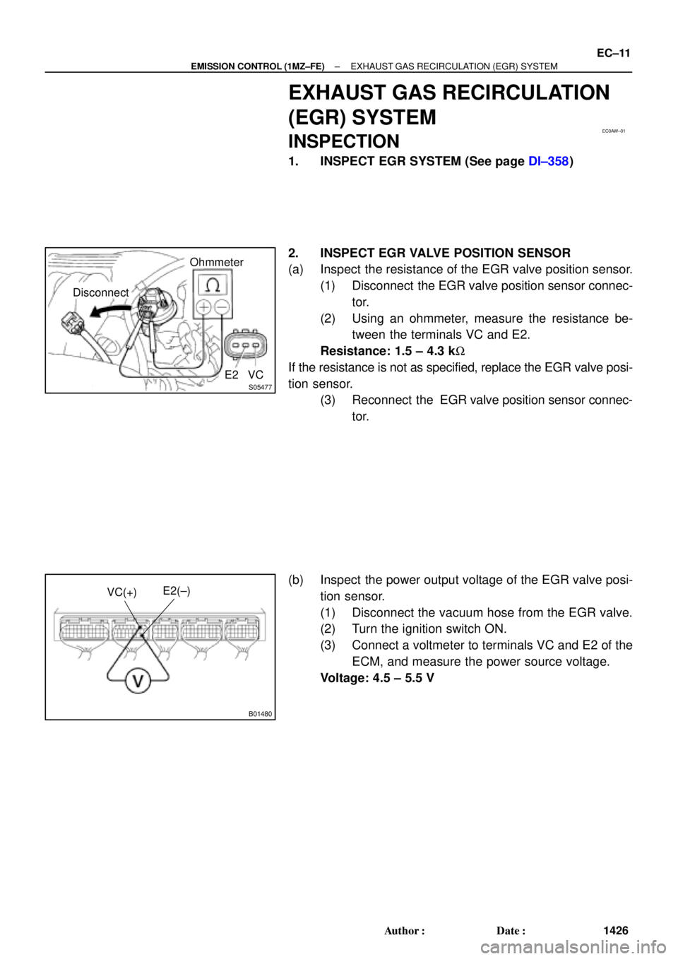
EC0AW±01
S05477
DisconnectOhmmeter
E2 VC
B01480
E2(±)
VC(+)
± EMISSION CONTROL (1MZ±FE)EXHAUST GAS RECIRCULATION (EGR) SYSTEM
EC±11
1426 Author�: Date�:
EXHAUST GAS RECIRCULATION
(EGR) SYSTEM
INSPECTION
1. INSPECT EGR SYSTEM (See page DI±358)
2. INSPECT EGR VALVE POSITION SENSOR
(a) Inspect the resistance of the EGR valve position sensor.
(1) Disconnect the EGR valve position sensor connec-
tor.
(2) Using an ohmmeter, measure the resistance be-
tween the terminals VC and E2.
Resistance: 1.5 ± 4.3 kW
If the resistance is not as specified, replace the EGR valve posi-
tion sensor.
(3) Reconnect the EGR valve position sensor connec-
tor.
(b) Inspect the power output voltage of the EGR valve posi-
tion sensor.
(1) Disconnect the vacuum hose from the EGR valve.
(2) Turn the ignition switch ON.
(3) Connect a voltmeter to terminals VC and E2 of the
ECM, and measure the power source voltage.
Voltage: 4.5 ± 5.5 V
Page 3386 of 4770
 EGLS(+)
S05452
S05455
(1)
(2)
(3)
EC±12
± EMISSION CONTROL (1MZ±FE)EXHAUST GAS RECIRCULATION (EGR) SYSTEM
1427 Author�: Date�:
(4) Connect a voltmeter to terminals EGLS an")
B01482
Disconnect
E2(±) EGLS(+)
S05452
S05455
(1)
(2)
(3)
EC±12
± EMISSION CONTROL (1MZ±FE)EXHAUST GAS RECIRCULATION (EGR) SYSTEM
1427 Author�: Date�:
(4) Connect a voltmeter to terminals EGLS and E2 of
the ECM, and measure the power outlet voltage un-
der the following conditions:
�Using a MITYVAC (Hand±Held Vacuum
Pump), apply a vacuum (17.3 kPa, 130
mmHg, 5.1 in.Hg) to the EGR valve.
Voltage: 3.2 ± 5.1 V
�Release the vacuum from the EGR valve.
Voltage: 0.4 ± 1.6 V
If the voltage is not as specified, replace the EGR valve position
sensor.
(5) Reconnect the vacuum hose to the EGR valve.
3. REMOVE EGR POSITION SENSOR
Remove the 3 nuts and EGR valve position sensor from the
EGR valve.
Torque: 2 N´m (20 kgf´cm, 17 in.´lbf)
4. REINSTALL EGR POSITION SENSOR
Installation is the reverse order of removal.
5. REMOVE EGR VALVE
(a) Remove the EGR pipe.
�Remove the 4 nuts, EGR pipe and 2 gaskets.
HINT:
At the time of installation, please refer to the following items.
Install 2 new gaskets.
Torque: 12 N´m (120 kgf´cm, 9 ft´lbf)
(b) Disconnect the EGR gas temperature sensor connector
and clamp.
(c) Remove the EGR valve.
(1) Disconnect the EVAP hose from the EGR valve
hook.
(2) Disconnect the vacuum hose from the EGR valve.
(3) Disconnect the EGR valve position sensor connec-
tor.
(d) Remove the 3 nuts, EGR valve and gasket.
HINT:
At the time of installation, please refer to the following items.
Install a new gasket.
Torque: 12 N´m (120 kgf´cm, 9 ft´lbf)
(e) Remove the EGR gas temperature sensor.
Torque: 20 N´m (200 kgf´cm, 14 ft´lbf)
Page 3390 of 4770
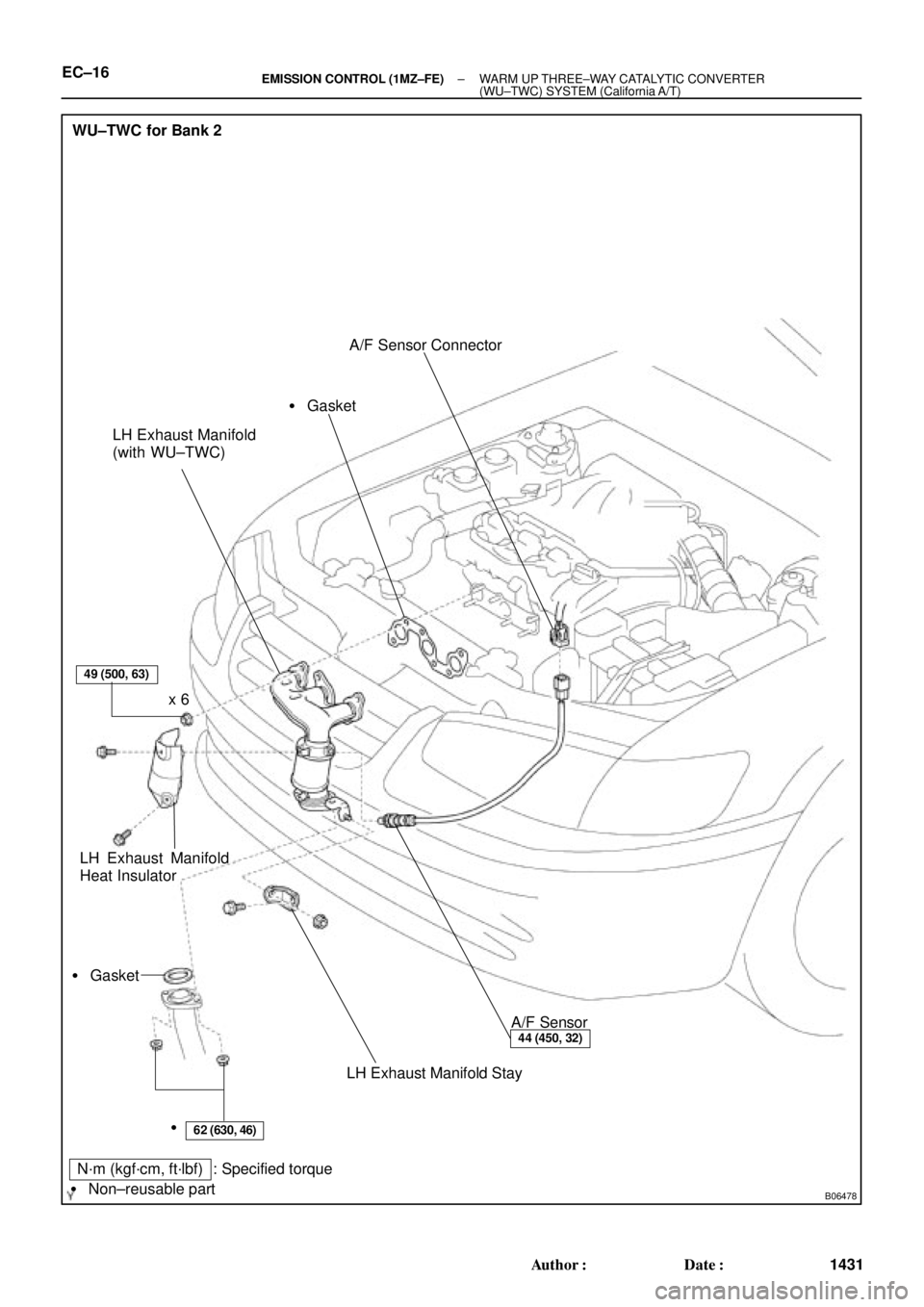
B06478
WU±TWC for Bank 2
LH Exhaust Manifold
(with WU±TWC)
LH Exhaust Manifold
Heat InsulatorA/F Sensor Connector
A/F Sensor
LH Exhaust Manifold Stay � Gasket� Gasket
49 (500, 63)
62 (630, 46)
44 (450, 32)
x 6
�
N´m (kgf´cm, ft´lbf) : Specified torque
� Non±reusable part
EC±16± EMISSION CONTROL (1MZ±FE)WARM UP THREE±WAY CATALYTIC CONVERTER
(WU±TWC) SYSTEM (California A/T)
1431 Author�: Date�:
Page 3394 of 4770
CO/HC
1174 Author�: Date�:
If the CO/HC concentration does not comply with regulations,
troubleshoot in the order given below.
(1) Check oxygen sensor operation.
(Se")
EM±2
± ENGINE MECHANICAL (5S±FE)CO/HC
1174 Author�: Date�:
If the CO/HC concentration does not comply with regulations,
troubleshoot in the order given below.
(1) Check oxygen sensor operation.
(See page DI±66)
(2) See the table below for possible causes, then in-
spect and correct the applicable causes if neces-
sary.
COHCSymptomCauses
NormalHighRough idle1. Faulty ignitions:
� Incorrect timing
� Fouled, shorted or improperly gapped plugs
� Open or crossed hi
gh±tension cords� Oen or crossed high±tension cords
2. Incorrect valve clearance
3. Leaky EGR valve
4. Leaky intake and exhaust valves
5. Leaky cylinder
LowHighRough idle
(Fluctuating HC reading)1. Vacuum leaks:
� PCV hose
� EGR valve
� Intake manifold
� Throttle body
� IAC valve
� Brake booster line
2. Lean mixture causing misfire
HighHighRough idle
(Black smoke from exhaust)1. Restricted air filter
2. Faulty SFI system
� Faulty pressure regulator
� Defective ECT sensor
� Defective IAT sensor
� Faulty ECM
� Faulty injector
� Faulty throttle position sensor
� MAP sensor

Heated Oxygen Sensor
(Bank 2 Sensor 1/
Except California A")