Page 3412 of 4770
TIMING BELT
1192 Author�: Date�:
(2) After aligning the matchmark, hold the timing belt.
And turn the crankshaft pull")
A02590TurnHold
S05612
SST
S05591
S05944
S05614
EM±20
± ENGINE MECHANICAL (5S±FE)TIMING BELT
1192 Author�: Date�:
(2) After aligning the matchmark, hold the timing belt.
And turn the crankshaft pulley counterclockwise,
and align its groove with timing mark º0º of the No.1
timing belt cover.
(b) Remove the pulley bolt.
(c) Using SST, remove the pulley.
SST 09950±50012 (09951±05010, 09952±05010,
09953±05010, 09953±05020, 09954±05020,
09954±05010)
HINT:
�Either of 2 types of pulley may be used, each with its own
bolt size, type A(09954±05020) and type B
(09954±05010).
�When re±using timing belt:
Remove the pulley without turning it.
14. REMOVE NO.1 TIMING BELT COVER
(a) Disconnect the crankshaft position sensor wire from the
clamp on the timing belt cover.
(b) Disconnect the clamp of the crankshaft position sensor
wire from the timing belt cover.
(c) Remove the 4 bolts and timing belt cover.
15. REMOVE TIMING BELT GUIDE
16. REMOVE TIMING BELT
HINT:
When re±using timing belt:
Draw a direction arrow on the timing belt (in the direction of en-
gine revolution), and place matchmarks on the timing belt and
crankshaft timing pulley.
17. REMOVE NO.1 IDLER PULLEY AND TENSION
SPRING
Remove the bolt, pulley and tension spring.
18. REMOVE NO.2 IDLER PULLEY
Remove the bolt and pulley.
Page 3413 of 4770
S05579
SST
S05575
SST
± ENGINE MECHANICAL (5S±FE)TIMING BELT
EM±21
1193 Author�: Date�:
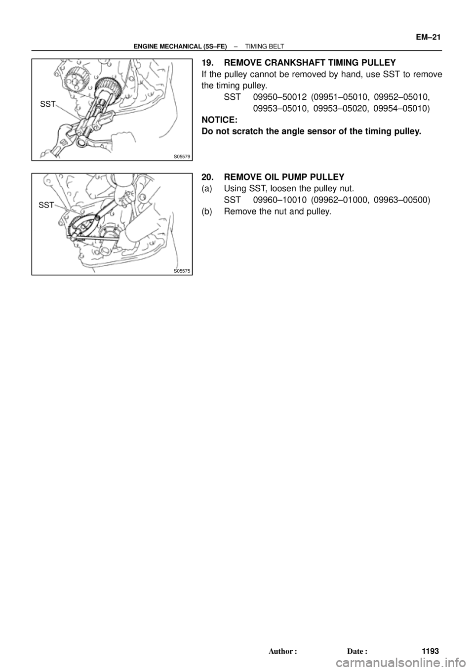
19. REMOVE CRANKSHAFT TIMING PULLEY
If the pulley cannot be removed by hand, use SST to remove
the timing pulley.
SST 09950±50012 (09951±05010, 09952±05010,
09953±05010, 09953±05020, 09954±05010)
NOTICE:
Do not scratch the angle sensor of the timing pulley.
20. REMOVE OIL PUMP PULLEY
(a) Using SST, loosen the pulley nut.
SST 09960±10010 (09962±01000, 09963±00500)
(b) Remove the nut and pulley.
Page 3415 of 4770
TIMING BELT
EM±23
1195 Author�: Date�:
INSTALLATION
1. INSTALL OIL PUMP PULLEY
(")
EM086±04
S05576
SST
S05577
Angle
Sensor
Inward
S05571
35 mm
S05616
42 mm
S05926
Pry
Move
± ENGINE MECHANICAL (5S±FE)TIMING BELT
EM±23
1195 Author�: Date�:
INSTALLATION
1. INSTALL OIL PUMP PULLEY
(a) Align the cutouts of the pulley and shaft, and slide on the
pulley.
(b) Using SST, install the pulley nut.
SST 09960±10010 (09962±01000, 09963±00500)
Torque: 24 N´m (245 kgf´cm, 18 ft´lbf)
2. INSTALL CRANKSHAFT TIMING PULLEY
(a) Align the timing pulley set key with the key groove of the
pulley.
(b) Slide on the timing pulley, facing the angle sensor inward.
NOTICE:
Do not scratch the angle sensor of the timing pulley.
3. INSTALL NO.2 IDLER PULLEY
(a) Install the pulley with the bolt.
Torque: 42 N´m (425 kgf´cm, 31 ft´lbf)
HINT:
Use the 35 mm (1.38 in.) long bolt.
(b) Check that the idler pulley moves smoothly.
4. TEMPORARILY INSTALL NO.1 IDLER PULLEY AND
TENSION SPRING
(a) Align the bracket pin hole with the pivot pin.
(b) Install the pulley with the bolt. Do not tighten the bolt yet.
HINT:
Use the 42 mm (1.65 in.) long bolt.
(c) Install the tension spring.
(d) Pry the pulley toward the left as far as it will go, and tighten
the bolt.
(e) Check that the idler pulley moves smoothly.
Page 3417 of 4770
TIMING BELT
EM±25
1197 Author�: Date�:
(b) Install the timing belt cover with the 4 bolts.
(c) Install the")
A02591
S05588
SSTSST
S05592
SST
SST
Fulcrum
Length
S05587
Turn
± ENGINE MECHANICAL (5S±FE)TIMING BELT
EM±25
1197 Author�: Date�:
(b) Install the timing belt cover with the 4 bolts.
(c) Install the clamp of the crankshaft position sensor wire to
the timing belt cover.
(d) Install the crankshaft position sensor wire to the clamp on
the timing belt cover.
8. INSTALL CRANKSHAFT PULLEY
(a) Align the pulley set key with the key groove of the pulley,
and slide on the pulley.
(b) Using SST (and bolt), install the pulley bolt.
SST 09213±54015 (91651±60855),09330±00021
Torque: 108 N´m (1,100 kgf´cm, 80 ft´lbf)
HINT:
Either of 2 types of pulley may be used, each with its own bolt
size, type A (91651±60855) and type B
(part No. 91121±40665).
9. INSTALL CAMSHAFT TIMING PULLEY
(a) Align the camshaft knock pin with the knock pin groove of
the pulley, and slide on the timing pulley.
(b) Using SST, install the pulley bolt.
SST 09249±63010, 09960±10010 (09962±01000,
09963±01000)
Torque:
54 N´m (550 kgf´cm, 40 ft´lbf)
37 N´m (380 kgf´cm, 27 ft´lbf) for use with SST
HINT:
Use a torque wrench with a fulcrum length of 340 mm (13.39
in.).
10. SET NO.1 CYLINDER TO TDC/COMPRESSION
(a) Turn the crankshaft pulley, and align its groove with timing
mark º0º of the No.1 timing belt cover.
Page 3421 of 4770
EM087±03
A02194
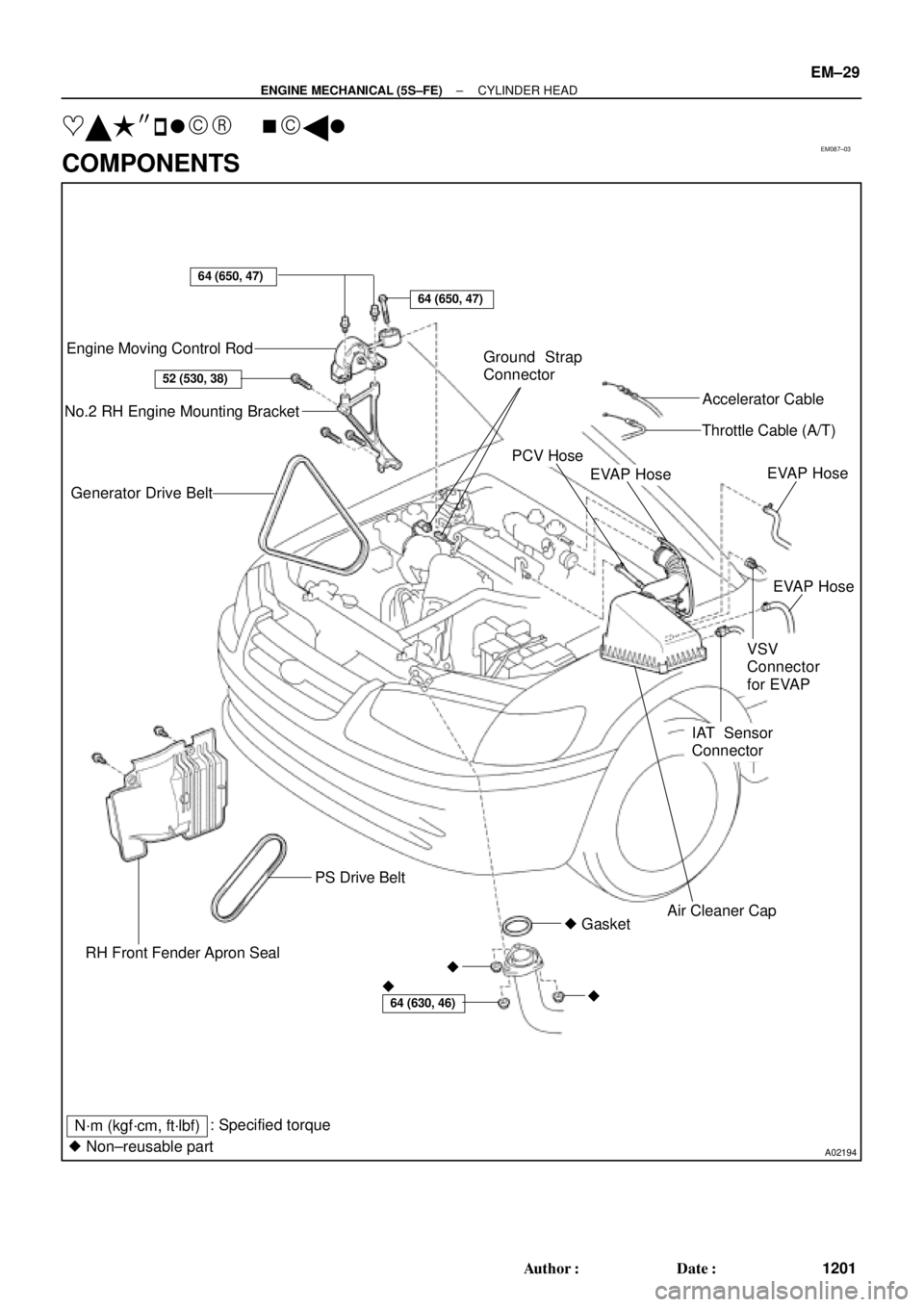
Engine Moving Control Rod
No.2 RH Engine Mounting Bracket
Generator Drive Belt
RH Front Fender Apron SealPS Drive Belt
� GasketAir Cleaner Cap
IAT Sensor
ConnectorEVAP Hose
VSV
Connector
for EVAPEVAP Hose
EVAP Hose
PCV HoseThrottle Cable (A/T)Accelerator Cable Ground Strap
Connector
N´m (kgf´cm, ft´lbf)
64 (650, 47)
64 (650, 47)
52 (530, 38)
64 (630, 46)� �
�
� Non±reusable part: Specified torque
± ENGINE MECHANICAL (5S±FE)CYLINDER HEAD
EM±29
1201 Author�: Date�:
���� ��
� ����
COMPONENTS
Page 3422 of 4770

A01562
Generator Wire
Generator
Connector
GeneratorWire Clamp
Wire
Clamp
ECT Sender
Gauge ConnectorThrottle BodyThrottle Position
Sensor ConnectorIgnition Coil Connector
IAC Valve
Connector
Heater Water Hose
Radiator Hose ECT Sensor
Connector
Water Outlet
Noise Filter Connector
Oil Pressure Switch Connector
Ignition Coil and No.2 Intake
Manifold Assembly
(with High±Tension Cord)
A/F Sensor Connector (California) or
Heated Oxygen Sensor (Bank 1 Sensor 1)
Connector (Except California)
(TMMK Made) � Gasket� Gasket � Gasket
(TMC Made)No.1 Exhaust
Manifold Stay
No.2 Exhaust
Manifold Stay No.1 Exhaust
Manifold Heat
Insulator
Exhaust Manifold,
No.2 and No.3
Exhaust Manifold
Heat Insulator
Assembly
� Non±reusable partExcept California
19 (195, 14)
49 (500, 36)
49 (500, 36)
: Specified torqueN´m (kgf´cm, ft´lbf)x 6
Exhaust Manifold,
No.2 and no.3
Exhaust Manifold
Heat Insulator
Assenbly
(California)
No.1 Exhaust
Manifold Heat
Insulator (California) (TMMK Made)
(TMC Made)
EM±30
± ENGINE MECHANICAL (5S±FE)CYLINDER HEAD
1202 Author�: Date�:
Page 3423 of 4770
A07358
Ground Wire
MAP Sensor
Vacuum Hose
Brake Booster
Vacuum Hose
Intake
Manifold
Air Hose for Air Assist System (California)
Intake Manifold
Stay
Injector
(Except California)
Knock Sensor 1
ConnectorPCV HoseVSV Connector
for EGR
VSV for EGREGR Valve and Vacuum
Modulator
Fuel Inlet Hose
Fuel Pulsation Damper
� O±Ring
Injector
(California)Injector
Connector Spacer
Insulator
N´m (kgf´cm, ft´lbf)
� Non±reusable part
� Gasket
� Insulator� Grommet
� O±Ring � Gasket� Gasket
* For use with SST
19 (195, 14)
34 (350, 25)* 29 (300, 21)
: Specified torque
x 6
Engine Wire
13 (130, 9)
Spacer
± ENGINE MECHANICAL (5S±FE)CYLINDER HEAD
EM±31
1203 Author�: Date�:
Page 3424 of 4770

A07368
Spark Plug
Grommet
Cylinder Head Cover
Gasket
Camshaft Bearing Cap
� Camshaft Oil Seal
Camshaft Timing Pulley
Snap Ring
Wave Washer
Camshaft Position Sensor Connector
Camshaft Position Sensor Assembly
Wire Clamp
No. 3 Timing Belt Cover
No.2 Timing Belt Cover� Oil Seal
Valve Guide
Bushing
Cylinder
Head
Gasket Adjusting Shim
Valve Lifter
Keeper
Spring Retainer
Valve Spring
Spring Seat
Valve
LH Engine
Hanger
Semi±Circular
Plug
Oil Pressure
Switch
Camshaft Gear Spring
Camshaft Sub±Gear
Semi±Circular
Plug
Tension Spring
No.1 Idler Pulley
*
1
GasketTiming Belt
Cylinder Head Intake
CamshaftExhaust
Camshaft
Wire
Clamp
Wire
Clamp
Generator Bracket and
RH Engine Hanger
Assembly
N´m (kgf´cm, ft´lbf)
*
2 For use with SST
� Non±reusable part
18 (180, 13)
44 (450, 33)
19 (190, 14)
*
237 (380, 27)1st 49 (500, 36)
2nd Turn 90°
42 (425, 31)
x 10�
�
: Specified torque
See page EM±53
*1
Replace only if damaged
54 (550, 40)
EM±32
± ENGINE MECHANICAL (5S±FE)CYLINDER HEAD
1204 Author�: Date�:

Intake Manifold
Stay
Injector
(Except California)
Knock Sensor 1
Connec")