Page 3425 of 4770
EM0YL±01
S05282
S05281
S05300
TMC
Made
TMMK
Made
S05297
Clamp
Sensor
Connector
± ENGINE MECHANICAL (5S±FE)CYLINDER HEAD
EM±33
1205 Author�: Date�:
REMOVAL
1. DRAIN ENGINE COOLANT
2. REMOVE AIR CLEANER CAP (See page EM±69)
3. REMOVE GENERATOR (See page CH±6)
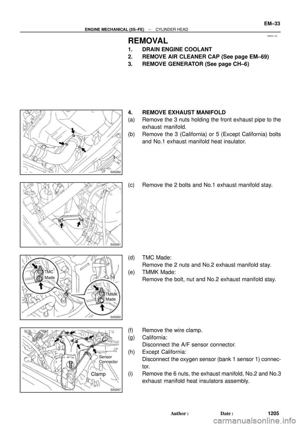
4. REMOVE EXHAUST MANIFOLD
(a) Remove the 3 nuts holding the front exhaust pipe to the
exhaust manifold.
(b) Remove the 3 (California) or 5 (Except California) bolts
and No.1 exhaust manifold heat insulator.
(c) Remove the 2 bolts and No.1 exhaust manifold stay.
(d) TMC Made:
Remove the 2 nuts and No.2 exhaust manifold stay.
(e) TMMK Made:
Remove the bolt, nut and No.2 exhaust manifold stay.
(f) Remove the wire clamp.
(g) California:
Disconnect the A/F sensor connector.
(h) Except California:
Disconnect the oxygen sensor (bank 1 sensor 1) connec-
tor.
(i) Remove the 6 nuts, the exhaust manifold, No.2 and No.3
exhaust manifold heat insulators assembly.
Page 3426 of 4770
(d)
(e)
A07364
ConnectorClamp
EM±34
± ENGINE MECHANICAL (5S±FE)CYLINDER HEAD
1206 Author�: Date�:
(j) California:
Disconnect the A/F sensor connector for the wiring side")
S05548
Wire
Clamp
A01564(c)(d)
(e)
A07364
ConnectorClamp
EM±34
± ENGINE MECHANICAL (5S±FE)CYLINDER HEAD
1206 Author�: Date�:
(j) California:
Disconnect the A/F sensor connector for the wiring side
from the bracket on the LH engine hanger.
(k) Except California:
Disconnect the heated oxygen sensor (bank 1 sensor 1)
connector for the wiring side from the bracket on the LH
engine hanger.
5. REMOVE THROTTLE BODY (See page SF±32)
6. REMOVE IGNITION COILS, NO.2 INTAKE MANIFOLD
STAY AND HIGH±TENSION CORDS ASSEMBLY
(a) Disconnect the 2 ignition coil connectors.
(b) Disconnect the 4 high±tension cords from the 2 clamps
on the cylinder head cover.
(c) Disconnect the 4 high±tension cords from the spark
plugs.
(d) Disconnect the wire clamp from the manifold stay.
(e) TMC Made:
Remove the 2 nuts, 2 bolts, 2 ignition coils, manifold stay
and 4 high±tension cords assembly.
(f) TMMK Made:
Remove the nut, 3 bolts, 2 ignition coils, manifold stay and
4 high±tension cords assembly.
7. DISCONNECT OIL PRESSURE SWITCH CONNECTOR
8. DISCONNECT NOISE FILTER CONNECTOR
9. REMOVE WATER OUTLET
(a) Disconnect the ECT sensor connector.
(b) Disconnect the ECT sender gauge connector.
(c) Disconnect the radiator hose from the water outlet.
(d) Disconnect the water bypass pipe hose from the water
outlet.
(e) Disconnect the heater water hose from the water outlet.
(f) Remove the 2 nuts, water outlet and gasket.
10. REMOVE INTAKE MANIFOLD STAY
Remove the bolt, nut and intake manifold stay.
11. REMOVE EGR VALVE AND VACUUM MODULATOR
(a) Disconnect the VSV connector for the EGR.
(b) Disconnect the hose clamp from the bracket on the intake
manifold.
(c) Remove the bolt, and disconnect the VSV for EGR from
the intake manifold.
Page 3427 of 4770

(b)(c)
A07360
(e)(d)
± ENGINE MECHANICAL (5S±FE)CYLINDER HEAD
EM±35
1207 Author�: Date�:
(d) Loosen the union nut of the EGR pipe, and remove the
bolt, 2 nuts,")
A07363
A07365
S05981
SST
S05990
(a)
(b)(c)
A07360
(e)(d)
± ENGINE MECHANICAL (5S±FE)CYLINDER HEAD
EM±35
1207 Author�: Date�:
(d) Loosen the union nut of the EGR pipe, and remove the
bolt, 2 nuts, the EGR valve, vacuum modulator, vacuum
hoses assembly and gasket.
12. DISCONNECT ENGINE WIRE FROM INTAKE MAN-
IFOLD
(a) Disconnect the engine wire clamp from the bracket on the
LH side of the intake manifold.
(b) Disconnect the 2 engine wire clamps from the 2 brackets
on the front side of the intake manifold.
13. DISCONNECT FUEL INLET HOSE FROM DELIVERY
PIPE
(a) Using SST, loosen the fuel pulsation damper.
SST 09612±24014 (09617±24011)
(b) Remove the fuel pulsation damper and 2 gaskets, and
disconnect the fuel inlet hose from the delivery pipe.
14. REMOVE INTAKE MANIFOLD
(a) Disconnect the MAP sensor vacuum hose from the gas
filter.
(b) Disconnect the brake booster vacuum hose from the in-
take manifold.
(c) Disconnect the PCV hose from the intake manifold.
(d) Remove the 2 bolts, and disconnect the 2 ground wires
from the intake manifold.
(e) Disconnect the knock sensor 1 connector.
Page 3432 of 4770
CYLINDER HEAD
1212 Author�: Date�:
25. DISASSEMBLE EXHAUST CAMSHAFT
(a) Mount the camshaft")
P05613
S01665
SST
Service
Bolt
S01666
EM7558
6 10
192 8 3
74 5
S05971
Pry EM±40
± ENGINE MECHANICAL (5S±FE)CYLINDER HEAD
1212 Author�: Date�:
25. DISASSEMBLE EXHAUST CAMSHAFT
(a) Mount the camshaft in a vise.
NOTICE:
Be careful not to damage the camshaft.
(b) Using SST, turn the sub±gear clockwise, and remove the
service bolt.
SST 09960±10010 (09962±01000, 09963±00500)
(c) Using snap ring pliers, remove the snap ring.
(d) Remove the wave washer, camshaft sub±gear and gear
spring.
26. REMOVE CYLINDER HEAD
(a) Disconnect the camshaft position sensor connector.
(b) Remove the 2 bolts holding the water bypass pipe to the
cylinder head.
(c) Uniformly loosen and remove the 10 cylinder head bolts
in several passes, in the sequence shown.
NOTICE:
Cylinder head warpage or cracking could result from re-
moving bolts in incorrect order.
(d) Lift the cylinder head from the dowels on the cylinder
block, and place the cylinder head on wooden blocks on
a bench.
HINT:
If the cylinder head is off, pry between the cylinder head and cyl-
inder block with a screwdriver.
NOTICE:
Be careful not to damage the contact surfaces of the cylin-
der head and cylinder block.
Page 3433 of 4770
EM089±03
P03265
SST
P03266
± ENGINE MECHANICAL (5S±FE)CYLINDER HEAD
EM±41
1213 Author�: Date�:
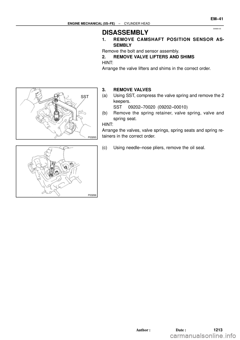
DISASSEMBLY
1. REMOVE CAMSHAFT POSITION SENSOR AS-
SEMBLY
Remove the bolt and sensor assembly.
2. REMOVE VALVE LIFTERS AND SHIMS
HINT:
Arrange the valve lifters and shims in the correct order.
3. REMOVE VALVES
(a) Using SST, compress the valve spring and remove the 2
keepers.
SST 09202±70020 (09202±00010)
(b) Remove the spring retainer, valve spring, valve and
spring seat.
HINT:
Arrange the valves, valve springs, spring seats and spring re-
tainers in the correct order.
(c) Using needle±nose pliers, remove the oil seal.
Page 3444 of 4770
CYLINDER HEAD
1224 Author�: Date�:
REASSEMBLY
HINT:
�Thoroughly clean all parts to be assemb")
EM0YM±01
P03274
SST
Z02903
Intake Exhaust
Gray
Black
P03265
SST
P03276
EM±52
± ENGINE MECHANICAL (5S±FE)CYLINDER HEAD
1224 Author�: Date�:
REASSEMBLY
HINT:
�Thoroughly clean all parts to be assembled.
�Before installing the parts, apply new engine oil to all slid-
ing and rotating surfaces.
�Replace all gaskets and oil seals with new ones.
1. INSTALL VALVES
(a) Using SST, push in a new oil seal.
SST 09201±41020
HINT:
The intake valve oil seal is gray and the exhaust valve oil seal
is black.
(b) Install the valve, spring seat, valve spring and spring re-
tainer.
(c) Using SST, compress the valve spring and place the 2
keepers around the valve stem.
SST 09202±70020 (09202±00010)
(d) Using a plastic±faced hammer, lightly tap the valve stem
tip to assure a proper fit.
2. INSTALL VALVE LIFTERS AND SHIMS
(a) Install the valve lifter and shim.
(b) Check that the valve lifter rotates smoothly by hand.
3. INSTALL CAMSHAFT POSITION SENSOR AS-
SEMBLY
Install the sensor assembly with the bolt.
Torque: 9.5 N´m (97 kgf´cm, 84 in.´lbf)
Page 3445 of 4770
CYLINDER HEAD
EM±53
1225 Author�: Date�:
INSTALLATION
1. PLACE CYLINDER HEAD ON CYLIND")
EM08D±04
A07355
Z02750
1
10 24 6 839
7 5
S01690
90°
Front
Painted
Mark90°
P03279
± ENGINE MECHANICAL (5S±FE)CYLINDER HEAD
EM±53
1225 Author�: Date�:
INSTALLATION
1. PLACE CYLINDER HEAD ON CYLINDER BLOCK
(a) Place a new cylinder head gasket on the cylinder block.
NOTICE:
Be careful of the installation direction.
(b) Place the cylinder head on the cylinder head gasket.
2. INSTALL CYLINDER HEAD BOLTS
HINT:
�The cylinder head bolts are tightened in 2 progressive
steps (steps (b) and (d)).
�If any cylinder head bolt is broken or deformed, replace
it.
(a) Apply a light coat of engine oil on the threads and under
the heads of the cylinder head bolts.
(b) Install and uniformly tighten the 10 cylinder head bolts
and plate washers in several passes, in the sequence
shown.
Torque: 49 N´m (500 kgf´cm, 36 ft´lbf)
If any one of the cylinder head bolts does not meet the torque
specification, replace the cylinder head bolt.
(c) Mark the front of the cylinder head bolt head with paint.
(d) Retighten the cylinder head bolts 90° in the numerical or-
der shown.
(e) Check that the painted mark is now at a 90° angle to the
front.
(f) Install the 2 bolts holding the water bypass pipe to the cyl-
inder head.
Torque: 19 N´m (195 kgf´cm, 14 ft´lbf)
(g) Connect the camshaft position sensor connector.
3. INSTALL SPARK PLUG TUBES
(a) Clean the cylinder head tube holes of any residual adhe-
sive, oil or foreign particles. Remove any oil with kerosene
or gasoline.
(b) Screw the threads of the spark plug tube coated with
adhesive into the cylinder head.
(c) Using the spark plug tube nut and a 30 mm socket
wrench, tighten the spark plug tubes.
Torque: 49 N´m (500 kgf´cm, 36 ft´lbf)
Page 3452 of 4770
A07362
Gray
Brown
No.1
No.2
No.3
No.4
A07361
California
A07359
S05990
(b)
(c)(d)
A07360
(e)
(f)
EM±60
± ENGINE MECHANICAL (5S±FE)CYLINDER HEAD
1232 Author�: Date�:
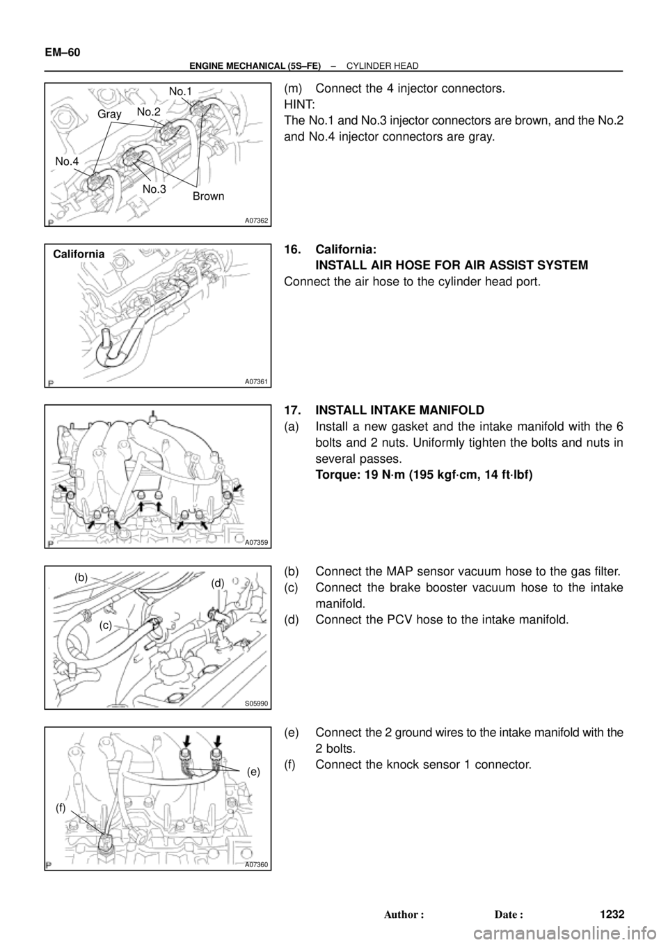
(m) Connect the 4 injector connectors.
HINT:
The No.1 and No.3 injector connectors are brown, and the No.2
and No.4 injector connectors are gray.
16. California:
INSTALL AIR HOSE FOR AIR ASSIST SYSTEM
Connect the air hose to the cylinder head port.
17. INSTALL INTAKE MANIFOLD
(a) Install a new gasket and the intake manifold with the 6
bolts and 2 nuts. Uniformly tighten the bolts and nuts in
several passes.
Torque: 19 N´m (195 kgf´cm, 14 ft´lbf)
(b) Connect the MAP sensor vacuum hose to the gas filter.
(c) Connect the brake booster vacuum hose to the intake
manifold.
(d) Connect the PCV hose to the intake manifold.
(e) Connect the 2 ground wires to the intake manifold with the
2 bolts.
(f) Connect the knock sensor 1 connector.